
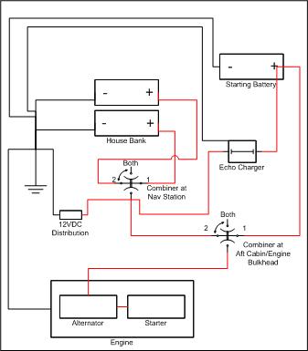
So, I have started to revisit my starting battery project, as my canvas project winds down. I have purchased a small starting battery (AGM) that will fit in the aft cabin hanging locker. I am thinking of wiring as shown in the diagram.
Again, thank you for all the great knowledge in the past and hope to get this completed for the early spring.
Just a few questions-
1. Is attaching the echo charger to the combiner switch (C poll) the correct connection point on for the charging source? This way I can charge with either house battery (2 4D AGMs)
2. Do I need to connect the start battery (neg) to the engine ground? or can it go to the main ground lug behind the distribution panel?
3. What would be the best route for the (pos) wire from Combiner at Aft Cabin/Engine bulkhead to the starting battery? I was planning on putting the combiner basically above the engine access hatch on the wall (oil dipstick access) in the aft cabin, unless someone has a better location? This way, I can utilize the current cable that goes from the alternator to the current combiner at the Nav Station and connect it to the new combiner on Poll 2 to the old combiner on Poll C.
4. Is it okay to splice the cables from the echo charger to the charging source and/or starting battery by bolting 2 "O" (ring terminals) together and then waterproof sealing them, or would this cause too much voltage drop?
Again, thank you for all your great knowledge and expertise in this matter.
Robert Trinkle
Troubador, 1995 C36 MKII #1433, SR/WK
Universal M35A
Kinsale Harbor Marina
Kinsale, VA
Robert,
Let me suggest some changes. First, I suggest you combine the house batteries into one house bank (in parallel), and run the alternator output directly to the house bank. You can use a new simple on/off battery switch for the house load, in place of the existing 1/2/B/O battery switch. Second, take out the wire connecting the alternator and the starter. Third, wire the new AGM starting battery directly to the starter, thru a battery switch. You can use the old 1/2/B/Off switch in a convenient spot if you want to (starting battery on 1, house bank on 2 for backup). Fourth, the Echo Charger is designed to be connected between the house bank and the starting battery, directly to their positive terminals. Fifth, get a good battery monitor to keep track of the house bank (not just a volt meter!) The starting battery, even being used every time you start the engine, doesn't need much attention. With the above changes, the alternator is always charging the house bank, and the echo charger is always charging the starting battery. Also with the above changes, the house load is coming off the house battery bank, and the engine is being started with the starting battery. When you come aboard the boat, you simply turn on the house battery switch, and turn on the starting battery switch. 99.9% of the time that's how you will leave it. No messing around trying to remember which battery is charging, discharging, in use, or idle. The above is how I wired Julandra, my current C400 Juniper, and is also how I've helped a bunch of friends wire their boats. It works, it's simple, and it takes away the "brother-in-law problem" ("Gee, I'm sorry...I didn't mean to switch the batteries off while the engine was running....) Make sure you use adequately sized wire, and make sure there are some fuses (large ones) close to the batteries to protect the wiring. For a couple of extra bucks, I would not try to skimp and join two too short wires together with lugs and bolts. It's just not worth it.
I've attached a diagram of Julandra's engine and chargine system. A few items need clarification. Emon is an energy monitor, Elim is an echo charger, and SAR is an external alternator regulator. Hope this helps.
Tom Sokoloski
C36/375IA Past Commodore
Noank, CT
Tom,
These are some great ideas. Connecting the alternator directly to the house bank to remove the possiblity of someone accidently turning off the combiner switch. That generates some new questions. Currently, the shore power charger charges each battery separately, on different banks of the charger. Can I leave it this way if the batteries are directly paralleled? I assume so, since when the current combiner is in the both position, the batteries are basically paralleled. Also, can I use the stock voltmeter instead of purchasing a new one?
However, I want to be able to isolate the house batteries for future upgrades, (i.e. going to 6VDC batteries instead of the current 4D 12VDC batteries.). I also like to switch between house batteries on odd and even days of our extended trips, especially in the late night when anchored. This is why I want to keep the combiner connected to the house batteries. On shorter trips, I like to keep the house batteries paralleled. Thus, keeping the echo charger pulling from both batteries equally at the combiner. This is why I asked about connecting the source of the echo charger to the current C poll on the combiner. Is it okay to connect the echo charger this way?
As for splicing and using the "O" ring terminals: The echo charger comes with the cables already terminated with the ring terminals. Would using a bolt and lug to splice be a big issue with safety and/or voltage drop? Either way, I would still need to splice a length of cable onto the existing echo charger cables. If it is a problem, what is the best way to splice the cables?
Robert Trinkle
Troubador, 1995 C36 MKII #1433, SR/WK
Universal M35A
Kinsale Harbor Marina
Kinsale, VA
[quote=rtrinkle]
I also like to switch between house batteries on odd and even days of our extended trips, especially in the late night when anchored. This is why I want to keep the combiner connected to the house batteries. On shorter trips, I like to keep the house batteries paralleled. [/quote]
If you already have a start battery on-board, this is a poor practice on many levels. While many think it is a good idea, using one large bank is the best approach.
[quote=rtrinkle]Thus, keeping the echo charger pulling from both batteries equally at the combiner. This is why I asked about connecting the source of the echo charger to the current C poll on the combiner. Is it okay to connect the echo charger this way?[/quote]
The Echo charger is intended and was designed to be directly wired to the house bank. It assumes you are using one contiguous house bank. It also assumes all charge sources feed directly to the house bank. Could the "C" post work? Yes, but it is not ideal, nor how it is or was intended to be used.
[quote=rtrinkle]As for splicing and using the "O" ring terminals: The echo charger comes with the cables already terminated with the ring terminals. Would using a bolt and lug to splice be a big issue with safety and/or voltage drop? Either way, I would still need to splice a length of cable onto the existing echo charger cables. If it is a problem, what is the best way to splice the cables?[/quote]
Use a good crimp tool and a heat shrink butt splice. Xantrex makes horrible factory crimps, with the wrong tool for the job, and they should ideally be cut off and re-terminated anyway.
For more on why splitting a house bank is a poor idea...
One Large Bank or Two Smaller Banks? http://forums.sbo.sailboatowners.com/showpost.php?p=1172783&postcount=5
-Maine Sail
https://www.marinehowto.com/
Like Apollo 13, I have inadvertently depleted a battery bank and having the ability to quickly bring online a fully charged reserve battery has made me look smart. I've traded some minor charging and monitoring inefficiencies for the capability this brings to the table.
Nick Caballero
Retired C36/375IA Mk II Technical Editor
Rob -
Here's a link to a prior thread where I posted a schematic of the wiring setup we now have:
https://www.catalina36.org/comment/47354#comment-47354
The schematic is also attached.
This was based on MaineSail's previous (and excellent) explanations at http://forums.catalina.sailboatowners.com/showthread.php?t=137615 (scroll down in that article to his section on "Alternate Methods and Switches")
In sum, we wired the alternator output directly to the "house bank" (which consists of 6V golf cart batteries). We added a Blue Seas Automatic Combiner Relay ("ACR"), which charges the "reserve bank" (which is a single 12V car battery) whenever there is a charge coming in from either the alternator or the battery charger. We reused the existing Off-1-2-Both battery switch, and added an On-Off battery switch for the "reserve" bank (labelled "Starter Disconnect Switch" in the schematic)-.
With this set-up, we essentially never have to bother with the switches in ordinary operation; they have no effect on charging and only control battery use. The house bank received charging current whenever the engine is running or the boat is plugged in at the dock or the sun is shining on the solar panels (not indicated on the sketch, as it was made before we added panels) -- regardless of what position the battery switch is set to (no risk of fried alternator diodes if someone turns the battery switch to "off") -- and that charging current gets sent over to the reserve battery as well via the ACR. The reserve battery also gets "exercised" regularly because its always used to crank the engine. In other words, there are no switches to fuss with or forget in normal operation; its fairly stupid proof.
With this rewiring scheme, there are thus 3 modes of operation:
I. Normal operation:
-Battery Switch put on “1" (supplying power from house bank only to the DC panel)
-Starter Disconnect Switch put on “On” (supplying power from reserve battery only to the starter)
II. Low "Reserve" battery:
-Battery Switch put on “Both” (supplying power from house bank to both DC panel and starter)
-Starter Disconnect Switch put on “Off” (to prevent a dead reserve battery from pulling down the house bank while cranking)
III. Low House bank:
-Starter Disconnect Switch “On”
- Battery switch put on “2" (supplying power from reserve bank to both DC panel and starter, and isolating dead house bank)
Matthew Chachère
s/v ¡Que Chévere!
(Formerly 1985 C36 MKI #466 tall rig fin keel M25)
2006 Catalina Morgan 440 #30.
Homeported in eastern Long Island, NY
Hey Matthew. Placing your switch in the "both" position totally defeats the Blue Seas, so you might want to consider adding an alarm to let you know the switch is in this position.
Anyway, pretty much the setup I have. Although I've eliminated the 1-2-both switch by wiring the DC panel to the house bank and installing a triple throw toggle switch on the Blue Seas control line to select the auto/combine/isolate functions. Most of the time, I'm in the "auto" mode and thus the Blue Seas decides when to combine and isolate. I've also added an alarm to the toggle switch when not in "auto" mode.
Nick Caballero
Retired C36/375IA Mk II Technical Editor
[quote=newguy] Placing your switch in the "both" position totally defeats the Blue Seas, so you might want to consider adding an alarm to let you know the switch is in this position.[/quote]
Of course it does. But unless I'm dealing with a dead (or near dead) battery, the switch never goes to "both".
Matthew Chachère
s/v ¡Que Chévere!
(Formerly 1985 C36 MKI #466 tall rig fin keel M25)
2006 Catalina Morgan 440 #30.
Homeported in eastern Long Island, NY
Robert,
Why put the starting battery in the hanging locker? We have a 2000, but I would guess the stock setup on your '95 is the same as ours with the 12V master panel set into the forward game table seat (if not just ignore this). There is ample room to mount a starting battery, and the existing wiring is all within a few inches. If I remember correctly I just need to pull a ground cable thru from the ground terminal strip. We generally use our house bank to start the engine, but mounted a separate starting battery there as a backup. I keep it charged with an ACR charging relay but an Echo Charger would work as well. I also shifted the wiring on the 1/2/B/OFF switch to consolidate the house batteries under the other seat as a single bank (position 1), and the backup battery as position 2. We just leave this switch to position 1 all the time, and turn the engine master on when we want to use the engine. If we ever ran the house bank down too far I could switch over to the backup and start the engine, and I could always use it to power the house loads if we had a failure of the house bank. Very easy to do this with the 12v panel right there. Also, I totally agree with Tom's comments, particularly running the alternator output directly to the house bank. Just make sure you fuse properly (7" from the terminal).
Mike Ogline
SHADOW #1831
2000 SR/WK
Deltaville - Chesapeake Bay
Mike,
Unfortunately, I do not have the same switch setup as you describe. I've seen that on other C36s, but I only have 1 A/B/Both combiner at the distribution panel over the chart table. A cable run from the engine to the starting battery in the aft cabin hanging locker would be a shorter run of cable.
I also plan on using the house bank for all the electrical needs, and use the starting battery as an emergency.
Robert Trinkle
Troubador, 1995 C36 MKII #1433, SR/WK
Universal M35A
Kinsale Harbor Marina
Kinsale, VA
Hello all,
I rewired my 86' MK 1 basically the same way as Tom. In my case, however, the house on/off switch is moved to the starting battery. This configuration allows the starting battery to be connected to the engine starting circuit completely independent of the house bank. The switch is actually a heavy duty key switch. In theory, you can take the key with you and no one can start engine even with access to the cabin. The reason (I was told) is that the former owner cruised outside the US and was concerned about someone stealing his boat.
Initially, I used an echo charge but found I could not fully charge the starting battery. In fact, it will deplete the starting battery some if there is any steady state current draw in the engine circuit. In my case, the starting battery powers the fuel lift pump, engine panel, and the bilge blower (I prefer to keep it that way). As a rule, I always run the bilge blower with the engine running to keep temperatures down in the engine compartment and to purge any exhaust fumes that may collect under the aft berth. Normally, that shouldn't happen but once it did because of a cracked inlet to the water lift muffler. I measured the steady state current in the engine circuit at 6 amps. The echo charge will provide that current if the voltage difference between the house bank and starting battery is 0.75 volts. The owners manual shows that curve. That means if the bulk charge for an AGM provided by the regulator on the alternator is 14.2 volts, the starting battery will see 13.5 v. After a while, the regulator will put out a float voltage at say 13.2 volts (I have a Balmer ARS-5 set up for AGM) which means the starting battery will see 12.5 v. That is too low to get a full charge. If the start battery began at 13.2 v (it should because of the AC battery charger and there is no current draw in the engine circuit), you have actually depleted the starting battery.
I always wondered why the start battery seemed weaker than normal even after motoring for several hours. Since then, I replaced it with a Blue Sea Systems solid state battery isolator switch. There is no longer any significant voltage difference between the starting battery and the house bank when the engine is running. The starting battery now sees the exact same voltage profile as the house bank. The echo charge literature is a little deceiving. It states that its internal circuitry is a voltage follower, but that is not entirely the case. If that were true, then I would have measured the exact same voltage at both the house bank and the starting battery with the engine running. It never was because of the current draw.
Regards,
John
Chachere has the exact same setup as mine. The 1/2/both bypasses the Blue Sea isolator but that is exactly what you need if the start battery is dead. Conversely, if the house bank is dead, you can use the start battery to run house loads. The only downside is if either bank is really truly dead or damaged. When the banks are shorted, a rush of current flows into the dead bank. That will deplete the good bank some and possibly a substantial amount. I considered that possibility but opted for a simpler setup.
Regards,
John
This is great information. Thank you all for your comments. Reading everything, I do have a few questions.
If the house batteries are directly paralleled, can I still keep the shore power charger connected the way it is already? Currently, I have a 3 bank charger. 2 of the banks are being used. Each of these 2 banks are directly connected to each house battery individually. I believe each bank is 10 AMPS, giving me the 30 amp charger. Is this correct?
If I connect the alternator directly to the house bank, what size fuze should I use, 50A? I have the stock alternator on the Universal M35 engine.
I see most people tend to use the ACR vs. the echo charger? Am I assuming the ACR is a better choice for this application? And why? Is it the current limiting of the echo charger? I looked at the BLUE SEA SYSTEMS "Add-A-Battery" Dual Circuit System. Will this suffice for my type of application? Looks like the price is about $20 more that the Xantrax Echo Charger.
Thanks for all your great words in this request. I'll work on another schematic and post when I'm done.
Robert Trinkle
Troubador, 1995 C36 MKII #1433, SR/WK
Universal M35A
Kinsale Harbor Marina
Kinsale, VA
I'd recommend just getting the Blue Seas ACR alone - ( www.bluesea.com/products/7610/SI-ACR_Automatic_Charging_Relay_-_12_24V_D... ) - NOT their "Add-A-Battery" package which throws in their Dual Circuit Plus battery switch (www.bluesea.com/products/5511e/e-Series_Dual_Circuit_Plus_Battery_Switch), a switch which only gives you less flexibility than your existing stock 1-2-Both switch. A longer discussion of the shortcomings of the "Dual Circuit Plus" switch is here: http://forums.catalina.sailboatowners.com/showthread.php?p=848465&highli... , but in sum, if you find ever yourself with a dead start battery and need to crank your engine from your house bank, the only option the Blue Seas Dual Circuit Plus battery switch offers is to be put in "combine" mode -- which really isn't what you want since then you're putting the dead battery in the same circuit as your house bank while trying to crank your engine (see schematic below copied from the Blue Seas' webpage for their switch). Why do that?
Instead, you can repurpose the existing 1-2-Both switch as described in some of the posts above and just add a straight On-off switch for the start battery, such as this one:
https://www.bluesea.com/products/9003e/e-Series_On_Off_Battery_Switch
Matthew Chachère
s/v ¡Que Chévere!
(Formerly 1985 C36 MKI #466 tall rig fin keel M25)
2006 Catalina Morgan 440 #30.
Homeported in eastern Long Island, NY
I can see the add a battery being an issue. If I got something like that, I would only use it as a disconnect switch for the starting battery. Any answers on my other questions?
Robert Trinkle
Troubador, 1995 C36 MKII #1433, SR/WK
Universal M35A
Kinsale Harbor Marina
Kinsale, VA
One more question if I may,,,, won't paralleling the house batteries cause larger charging times when running the engine, when at anchor from the engine, or from shore power?
Robert Trinkle
Troubador, 1995 C36 MKII #1433, SR/WK
Universal M35A
Kinsale Harbor Marina
Kinsale, VA
Robert,
In answer to some of your questions above, the type and configuration of your battery charger determines how much each output terminal will receive. It would be best to contact the manufacturer of your battery charger to be sure, but usually the total output of the charger is divided up between the batteries (banks) connected. Normally, if you have two banks connected, then each one would receive 15A. With three batteries connected, each one would received 10A. Leaving your two house batteries each connected to a charger output terminal should be fine, but if the manufacturer says that each terminal receives 10A, then it might be a good idea to put jumpers between the output terminals to feed all 30A to one terminal, and remove one of your current charging wires.
The OEM alternator is rated at 55A. A 50A fuse would probably work, but you might want to consider a 75A fuse in that line.
Wiring the house batteries in parallel will not cause longer charging times. Using more amps will cause longer charging times. Wiring the house batteries in parallel is also better for the batteries. Let me give an example. Let's say you routinely use 50AH between charges, and let's say each of your house batteries is a 100AH deep cycle battery. If you use each battery individually, you will be depleting each battery to 50% SOC (state of charge) between charges. If you parallel the batteries, you will in effect have a single 200AH battery. Using the same 50AH between charges will only be depleting the bank to 75% SOC. Any battery manufacturer will tell you that the less you discharge a battery, the better it is for the health of the battery. Hope this helps.
Tom Sokoloski
C36/375IA Past Commodore
Noank, CT
Tom,
Thank you for your response. I will check on the charger my next trip to the boat. But I think you are correct, it is probably using 15 amps on each battery now. Therefore, unless the documentation tells me different, I will probably keep it connected as is.
Also, I understand the reasoning for paralleling the house batteries. We currently have 2x 200 Ahr AGM 4D batteries. When it comes time to replace them, I want to move to the 6V batteries. They are lighter and easier to manage. In that configuration, if one battery goes bad, then both batteries in series will need to be taken offline. Therefore, I am thinking of keeping the 1/2/both combiner in place as it is now, and always keep it in the Both position, and run the alternator directly to one battery. That should provide the same alternator charge as paralleling the batteries at the battery terminals, correct? Unless there is a better setup that I'm not thinking about.
Robert Trinkle
Troubador, 1995 C36 MKII #1433, SR/WK
Universal M35A
Kinsale Harbor Marina
Kinsale, VA
"That should provide the same alternator charge as paralleling the batteries at the battery terminals, correct?"
Correct.
Tom Sokoloski
C36/375IA Past Commodore
Noank, CT
So I have a great idea on my starting battery upgrade. One last idea on the configuration.
I see many use a battery monitor. Currently, I have a analog volt meter that goes to both house batteries (believed to be stock install, as the install looks too good for an upgrade mounted on the DC distribution panel), and an amp meter showing current consumption, which looks like a previous upgrade. Will this suffice, or should I get a new battery monitor? If I need a new battery monitor, can I use the current Neg configuration, and just tie into the current ground, or do I need to put in a new negative shunt? If I need a new battery monitor, what would you recommend. I don't want to break the bank, but don't want to go to cheap either. So a good middle of the road, or slighty high end.
Robert Trinkle
Troubador, 1995 C36 MKII #1433, SR/WK
Universal M35A
Kinsale Harbor Marina
Kinsale, VA
Robert -
Your current (pardon the pun) set up really doesn't give you much useful information. For example, the analog volt meter is not going to give you sufficiently precise numbers, and you have no easy way to assess the amount of amp hours you have left or track consumption. A good battery monitory eliminates a lot of guesswork.
We installed a Victron 602 monitor ( http://www.victronenergy.com/upload/documents/Datasheet-Battery-monitori... ) a few years ago, which separately monitors both the house and the start battery banks; it comes with a shunt. It fit right in the panel opening on our boat where the original analog volt meter was located. I think there's a newer model now, the 702; it runs around $200.
Mainesail's excellent site ( http://www.pbase.com/mainecruising/boat_projects ) has some good write-ups about battery monitors and what they can do for you, such as these:
http://www.pbase.com/mainecruising/battery_monitor
http://www.pbase.com/mainecruising/smart_gauge
Matthew Chachère
s/v ¡Que Chévere!
(Formerly 1985 C36 MKI #466 tall rig fin keel M25)
2006 Catalina Morgan 440 #30.
Homeported in eastern Long Island, NY
Robert,
What Matthew said. Check out MaineSail's excellent website, and you will gain some valuable information. The newer energy monitors are light years ahead of what you have now. Absolutely money well spent, IMHO.
Tom Sokoloski
C36/375IA Past Commodore
Noank, CT
In regards to Ah counting "battery monitors" perhaps my most important article yet.... (wink)
Programming A Battery Monitor
http://www.pbase.com/mainecruising/programming_a_battery_monitor
-Maine Sail
https://www.marinehowto.com/
[quote=Maine Sail]In regards to Ah counting "battery monitors" perhaps my most important article yet.... (wink)
Programming A Battery Monitor
http://www.pbase.com/mainecruising/programming_a_battery_monitor[/quote]
I had considered linking that article in my prior reply, Maine, but didn't want to scare Robert off (as you yourself write at at one point in your article, "My Freaking Head is Spinning......").
Seriously, its a lot to get through, but very helpful -- once I wrapped my head around it -- to understanding the limits of what these devices do (particularly if not properly programmed), and understanding battery behavior in general.
As always, thanks for all you do to explain this stuff to us mere mortals, Maine.
Matthew Chachère
s/v ¡Que Chévere!
(Formerly 1985 C36 MKI #466 tall rig fin keel M25)
2006 Catalina Morgan 440 #30.
Homeported in eastern Long Island, NY
Unfortunately there is no easy way to explain properly using a battery monitor nor is there an easy way to explain how they work, reset etc.... I tried to make it as easy as I could but I suspect for most it will require at least two reads to get it to absorb......
-Maine Sail
https://www.marinehowto.com/
On "Programming a Battery Monitor", Maine Sail's usually stellar prose is nowhere to be seen. This document is way too lengthy, is way too much of a rant, and is certainly not very helpful. I wish Rod would rewrite it in Tech Writer Prose, logically presented so that I could get more out of it.
I just installed a LinkPro, in (what I think is) a beautiful installation which goes on my long list of things to write up for the C36IA. But before I plugged in the two fuses, I re-read all the info that came with the LinkPro. And then I read my printed out copy of Rod's essay. Here are my thoughts:
1. The LinkPro is a super fine voltmeter, giving accurate DC voltage at the push of a button.
2. It also gives instantaneous current draw at the push of a button.
3. Given 1 and 2 above, it SHOULD be able to calculate and sum Amp hour draw subsequent to a prior synchronization.
OK, the above three items alone make the thing worthwhile for me. I now have MUCH more information than I ever had, and I can personally monitor and log these values as desired.
I think where Maine Sail goes off on a rant - probably rightly - is regarding the monitor's calculation of State of Charge (SOC). Because of many reasons itemized in his essay, it is extremely difficult to know the available Amp hours remaining in any topped-off battery that hasn't been bench checked per his process. If this is a correct interpretation of his essay, then I agree. Even so, items 1, 2 and 3 above OUGHT to be accurate. He has convinced me to NOT USE the SOC readout at all. I intend to ignore it entirely.
What I have decided to do with my new monitor is to first use it as a voltmeter, and to establish a lower voltage limit that will be my Do Not Pass limit. Rod refers to 10.5 volts as a candidate for that value; but I intend to use something between 10.75 and 11.25 Volts. I'll probably start at 11.25 VDC, but to decide this after seeing what life is like on the hook.
Rod, sorry to be so tough on you for your article, but it really needs to be rewritten.
Larry Brandt
S/V High Flight #2109
Pacific Northwest, PDX-based
2002 C-36 mkII SR/FK M35B
[quote=LCBrandt]Maine Sail's usually stellar prose is nowhere to be seen. (EDIT: snipped due to 3k limit)[/quote]
I don't know when you read it but it has been edited multiple times and the "rantiness" should have toned down quite a bit.. The day I posted that link the article was just being written & edited. Unfortunately with my current site everything is done it real time and I don't have a edit then publish feature. The new site is only a few weeks away though!!!
That article is long and in-depth but I have really only scratched the surface. It could be way more in-depth... I tried very hard to balance it for the non-technical and technical reader too. I guess I can't please everyone....
[quote=LCBrandt]
1. The LinkPro is a super fine voltmeter
2. It also gives instantaneous current draw
3. it SHOULD be able to calculate and sum Amp hour draw [/quote]
1 = Yes
2 = yes
3= It calculates energy removed with great accuracy! However what that actually means to the battery is not what the -Ah's screen says unless you did so at the 20 hour rate and at 75F - 80F.
[quote=LCBrandt]
where Maine Sail goes off on a rant is regarding the monitor's calculation of State of Charge (SOC). [/quote]
SOC is what these devices really need to track to give the most efficient use of the bank and to get the most life.
[quote=LCBrandt]items 1, 2 and 3 above OUGHT to be accurate. [/quote]
Yes they are all accurate but #3 will not be accurate against your banks actual SOC...
[quote=LCBrandt]convinced me to NOT USE the SOC readout at all.[/quote]
This is really sad and a clearly failure of mine. This article is very, very, very tough for most to comprehend and hence why it took me many years to begin to even tackle it.....
[quote=LCBrandt]Rod refers to 10.5 volts as a candidate for that value;[/quote]
Again a FAILURE of mine, and the article has been edited with a WARNING.
You should really not be going below 11.8V - 12.0V (loaded at average ships current) but this will neeed to be confirmed by using your average current & loaded voltage at average current then letting the batteries rest for 24 hours at 75-80F to determine what the loaded voltage means in relation to the resting open circuit voltage. If you discern that an 11.8V "loaded" voltage results in a 12.10V resting voltage, and you have Trojan batteries, then 11.8V, at your average house load, is approx 50% SOC and time to recharge and you should not dip below this unless using a short duration hig draw item.
[quote=LCBrandt]Rod, sorry to be so tough on you
[/quote]
Not a problem, I always welcome constructive criticism. I have made multiple edits. I am sorry you got so little out of it. I have many emails from folks who now have better performing monitors and loved it.
-Maine Sail
https://www.marinehowto.com/
Tom and Matt,
I find myself looking at your scheme more and more, and am thinking of using it. Where did you physically install the starting battery disconnect switch, and the starting battery? Currently I only have 1 combiner switch at the chart table on the distribution panel.
Robert Trinkle
Troubador, 1995 C36 MKII #1433, SR/WK
Universal M35A
Kinsale Harbor Marina
Kinsale, VA
Robert -
I have a MkI, so the distribution panel is somewhat different than that on your MkII. On ours, originally the fuel gauge was mounted on the distribution panel at the nav table, which I found rather inconvenient (especially when refueling, as I had to run back and forth to check how close we were to full), so I moved it to the engine panel at the helm (in the place of the useless and redundant analog voltage gauge at the helm). This left a nice hole in the electrical panel where I then installed the disconnect switch (had to slightly enlarge the hole for it to fit). Picture posted below.
On the other hand Tom created a whole new distribution panel (that's fairly way down my to-do list!) and then mounted the two battery switches in a separate panel below it. Here are links to his photos:
https://julandra.shutterfly.com/189
https://julandra.shutterfly.com/191
Matthew Chachère
s/v ¡Que Chévere!
(Formerly 1985 C36 MKI #466 tall rig fin keel M25)
2006 Catalina Morgan 440 #30.
Homeported in eastern Long Island, NY
Thanks for the info. Since my distribution panel is over the nav table on the starboard bulkhead, I was thinking of putting the disconnect in the locker above the aft starboard settee. That way it is out of the way, hidden, and still relatively close to the combiner which is mounted on the distribution panel. Next time I'm at the boat, I'll take a picture and post it.
Robert Trinkle
Troubador, 1995 C36 MKII #1433, SR/WK
Universal M35A
Kinsale Harbor Marina
Kinsale, VA
Thanks to everyone for there input on this project. I have picked up the ACR today and began looking over the instructions. What AWG size wire would you recommend for the ACR to starting battery, and ACR to house battery, and what size fuzes? The cable run should be between 7 and 10 feet going from the aft settee to the fwd settee. I'll be putting the starting battery in the fwd settee and the ACR in the aft settee with the house bank. The new on/off switch (for the starting battery to starter via the combiner) will be located in the locker above the aft settee to give me a short run between the on/off switch and the combiner.
Also, what AWG wire size would you recommend for the starting battery to starter? Since the conduit running behind the bulkhead is relatively tight with cables already in there, i would like to keep the wire size as small as possible. I'll also repurpose the current cable from the alternator to the combiner for the connection between the starter and combiner.
Again I've decided to use the same configuration as John and Chachere (Matthew).
Robert Trinkle
Troubador, 1995 C36 MKII #1433, SR/WK
Universal M35A
Kinsale Harbor Marina
Kinsale, VA
Your sketch looks good. A couple of small points.
1) Ideally, the house bank should be completely protected by a fuse no more than 7" from the positive terminal, if possible, if I'm remembering the standard. Many of your lines coming from the house bank are not fused. A fuse block on the battery terminal itself could handle this.
2) Also, you might consider running the alternator cable to the ACR instead, then its just a short jumper to the house bank positive.
3) Don't see your battery charger in there, but assume you've figured that in.
Matthew Chachère
s/v ¡Que Chévere!
(Formerly 1985 C36 MKI #466 tall rig fin keel M25)
2006 Catalina Morgan 440 #30.
Homeported in eastern Long Island, NY
Matthew,
Your ideas sound good, I will incorporate them.
I'm assuming I should use the same AWG cable for the starting circuit as the boat originally came with? If I could go any smaller, what would recommend as the AWG cable size?
What size AWG cable should I use for the ACR for both battery banks and the alternator? Would the 75amp fuze be sufficient for the ACR to both batteries? And I'm assuming a battery terminal fuze would work for both battery banks?
One last thing, do you have a fuze between the neg on the ACR and ground? If so what rating fuze and what AWG size cable should I use for this ground circuit?
Thanks again for all your help.
Robert Trinkle
Troubador, 1995 C36 MKII #1433, SR/WK
Universal M35A
Kinsale Harbor Marina
Kinsale, VA
[quote=rtrinkle]
I'm assuming I should use the same AWG cable for the starting circuit as the boat originally came with? If I could go any smaller, what would recommend as the AWG cable size?
What size AWG cable should I use for the ACR for both battery banks and the alternator? Would the 75amp fuze be sufficient for the ACR to both batteries? And I'm assuming a battery terminal fuze would work for both battery banks?
One last thing, do you have a fuze between the neg on the ACR and ground? If so what rating fuze and what AWG size cable should I use for this ground circuit?
[/quote]
As to the first item, I wouldn't make that assumption, and certainly would NOT go smaller; some of the OEM wiring was undersized. As explained by Soko in this thread -- https://www.catalina36.org/comment/50281#comment-50281 -- you need to figure out the entire round-trip distance, and the potential amperage load and acceptable voltage drop. Loads depends on several factors, including the size of your alternator (i.e., output). Same vis-a-vis the starter's draw.
Nigel Calder's book "Boatowner's Mechanical and Electrical Manual" (a very useful reference to have, if you don't already) has tables you can use to calculate this, or you can find them via Googling around. See, e.g., Table 1: Wire Gauge for 3% Voltage Drop at 12 Volts about 1/3 of the way down in this article: http://www.boatus.com/boattech/articles/choosing-cables-and-terminals.asp
On my boat its about a 20-25' round trip from the alternator to the house bank and back, with all the twists and turns. With a 55 amp alternator, according to the above-reference table I was on the borderline between the stock 4ga cable that came with the boat and 2ga, but when rewiring to connect the alternator directly to the housebank/ACR I used 1ga (this might have been slightly overdoing it, but seemed like a good idea for the possibility that we might someday upgrade to a larger alternator; you can't go wrong oversizing.) You'll need to figure in the longer run from the starter all the way to the starter battery (sounds like that could add to to around 40'?). See also discussions here: https://www.catalina36.org/forum/technical-discussion/boat-battery-blues...
I'm not sure I understand most of your questions about fusing; this may help: http://www.pbase.com/mainecruising/battery_fusing
But as to your last question on fusing the negative on the ACR, the recommendations of Blue Seas in their instructions show the negative connection on the ACR is made with 16ga wire and a 10amp: http://assets.bluesea.com/files/resources/instructions/990170140.pdf
Matthew Chachère
s/v ¡Que Chévere!
(Formerly 1985 C36 MKI #466 tall rig fin keel M25)
2006 Catalina Morgan 440 #30.
Homeported in eastern Long Island, NY
Matthew,
I was down at the boat this weekend putting on the sails and snaking messenger lines for the cables. Here's what I have, and what I plan to do. Just to make sure I'm not missing anything:
1. House bank charging:
a. Currently- 1/0 AWG cable from starter/alternator to combiner switch.
b. Plan to - Disconnect starter from alternator. Add 1/0 AWG from alternator to ACR, (20 Ft). Put a 75 amp terminal block fuze on the battery terminal. Add a 4/0 AWG cable from ACR to house bank (9.5 foot run).
Since the terminal block fuze will be directly connected to the POS terminal on the battery, I'm assuming this is enough for both the charging and the starting circuits, as all connections would be tied together at the fuze.
2. Starting battery charging circuit:
a. Currently - No starting battery
b. Plan to - Use 4/0 AWG from ACR to starting battery (ACR in Nav desk to battery in fwd settee), (13 ft) run. Put a 75 amp terminal block fuze on the battery terminal. Ground connection ( 1/0 AWG - 1 ft run) to ground connection already in fwd settee.
2. Starting battery-starting circuit
a. Currently- No starting battery.
b. Plan to - 1/0 AWG cable from starting battery to disconnect switch and then disconnect switch to starter. (Batttery to disconnect switch - 13 ft), (disconnect switch to combiner - 2 ft).
The reason I plan on using 4/0 AWG cable for charging circuits, is the onboard charger is using that same size cable to the house batteries.
Thanks for all your advise. Anyone else that has some idea, please do. I'm all ears.
Robert Trinkle
Troubador, 1995 C36 MKII #1433, SR/WK
Universal M35A
Kinsale Harbor Marina
Kinsale, VA
[quote=rtrinkle]
Matthew,
I was down at the boat this weekend putting on the sails and snaking messenger lines for the cables.
[/quote]
You're putting on the sails already? I'm jealous; we're a long way from there in NY at the moment...
[quote=rtrinkle]
1. House bank charging:
a. Currently- 1/0 AWG cable from starter/alternator to combiner switch.
b. Plan to - Disconnect starter from alternator. Add 1/0 AWG from alternator to ACR, (20 Ft). Put a 75 amp terminal block fuze on the battery terminal. Add a 4/0 AWG cable from ACR to house bank (9.5 foot run).....
2. Starting battery charging circuit:
a. Currently - No starting battery
b. Plan to - Use 4/0 AWG from ACR to starting battery (ACR in Nav desk to battery in fwd settee), (13 ft) run. ... [/quote]
A few thoughts
1) I had originally started to install the ACR in the Nav desk behind the distribution panel in our boat, but after reviewing the Blue Seas ACR instructions -- which if I recall indicate that it should be installed as close to the batteries as possible (to avoid voltage drops that would impair its correct voltage sensing) -- it seemed better to put it in the battery compartment so that the cable runs were as short as possible. See discussion at https://www.catalina36.org/forum/technical-discussion/battery-compartmen....
2) Although you indicated you are planning to use 4/0 ga to connect the batteries to the ACR, I'm assuming you meant to write 4ga, since 4/0 ga are monstrously thick cables and would seem to be overkill.
With that assumed, I'd have concerns about switching to 4ga to connect the ACR to the batteries (or at least to the house bank). First, because of the possible adverse effect on the ACR's accuracy in sensing the batteries' voltage, as discussed above. And secondly, because I think you need to contemplate the minimum requirements for the ENTIRE circuit from alternator to ACR to house bank back to alternator (via engine ground). If you've calculated that it should be wired in 1ga cable, then it seems to me that running a portion of this circuit using 4ga cable defeats the purpose, no? (similar to a chain being only as strong as its weakest link). (Mind you, I claim no training or credentials in this or any other aspects of boats, just thinking out load as a tinkerer).
3) I'm not fully familiar with the layout of Mark IIs, but II have a vague recollection of reading here that some owners of those models have installed the start battery under the berth of the aft cabin, which would result, I imagine, in significantly shorter cable runs than putting it in the forward starboard settee....Ah, here's a link: https://tomsenatorc36projects.shutterfly.com/48
Matthew Chachère
s/v ¡Que Chévere!
(Formerly 1985 C36 MKI #466 tall rig fin keel M25)
2006 Catalina Morgan 440 #30.
Homeported in eastern Long Island, NY
Yes, you are correct, I was thinking about 4ga, not 4/0. That was because the shore power charger is all 4ga from the charger to the house batteries. After reading your previous post and looking up the cable size to length, I was actually thinking of going to 1ga.
I also looked at the possibility putting the start battery behind the engine, but that would require an extremely long run from the ACR to the starting battery. Having the ACR closer to the batteries, is something I will look at closer. I'll have to add some mounting brackets in the battery compartment, but I think a 2x4 primed and sealed would be cheaper than the extra length of 1/0 AWG and 1ga wire, and the sweat equity to remove the batteries and move the ACR to the battery compartment would definitely shorten all charging cable runs, reducing the cost of the cables. I bet I could drop 3 ft + off of each cable!
Thanks for all your advise.
BTW, here's where the combiner is on my boat.. As well as the volt meter, that will eventually be replaced this summer with the new BlueSea's monitor 1830 coming out this summer.
Robert Trinkle
Troubador, 1995 C36 MKII #1433, SR/WK
Universal M35A
Kinsale Harbor Marina
Kinsale, VA
[quote=rtrinkle]... Having the ACR closer to the batteries, is something I will look at closer. I'll have to add some mounting brackets in the battery compartment, but I think a 2x4 primed and sealed would be cheaper ... [/quote]
I certainly don't think you need anything that massive to mount the ACR. A little piece of plywood epoxied to the hull side of the battery compartment under the aft starboard seat should do. In my boat, I was able to just through-bolt it to the forward side of that compartment
One other location for the start battery you might consider is in the compartment behind the upper seat back cushion of the aft seat, just above the existing battery compartment. You might have to slightly enlarge the opening... if you look at Soko's pictures of Julandra, https://julandra.shutterfly.com/195 he managed to cram a group 31 battery in there as part of his house bank, A group 27 size would likely be adequate for a starter battery and would fit easier..... (actually, your first posting in this threat indicated that you had already purchased a small battery for this purpose).
Matthew Chachère
s/v ¡Que Chévere!
(Formerly 1985 C36 MKI #466 tall rig fin keel M25)
2006 Catalina Morgan 440 #30.
Homeported in eastern Long Island, NY
So is there any good place to purchase the cabling? West Marine has it for 6.99/ft. That is bloody expensive!!
Robert Trinkle
Troubador, 1995 C36 MKII #1433, SR/WK
Universal M35A
Kinsale Harbor Marina
Kinsale, VA
Robert,
That's an easy one:
http://www.genuinedealz.com/
Tom Sokoloski
C36/375IA Past Commodore
Noank, CT
Sounds good to me. I'll check it out.
I did find a 8 ton hydraulic press for AWG 12 - 2/0 cable for $40.00. I suppose 8 ton is enough pressure.
Robert Trinkle
Troubador, 1995 C36 MKII #1433, SR/WK
Universal M35A
Kinsale Harbor Marina
Kinsale, VA
So here is my idea on Tom's upgrade of Julandra. I know the combiner is still used for paralleling the house bank, but if I upgrade the house batteries to 6v, being able to isolate the house batteries incase a single battery goes bad is important. I like this idea, b/c I can keep the fwd stbd settee clear of tools and starting battery and move it to the aft cabin out of the way. Please let me know what you think, everyone...
Robert Trinkle
Troubador, 1995 C36 MKII #1433, SR/WK
Universal M35A
Kinsale Harbor Marina
Kinsale, VA
[quote=rtrinkle]if I upgrade the house batteries to 6v, being able to isolate the house batteries in case a single battery goes bad is important. [/quote]
1) Why would it be more important with 6v house batteries than if you have 12v house batteries?
2) Frankly, I don't see the value in setting up the 1-2-Both switch in this manner solely for the rare possibility of one of your house batteries getting a dead cell. Seems to me you if that happened you could just remove and reconnect cables to isolate the problem battery. In any event, on your schematic, if you used the 1-2-Both switch to isolated the right-hand house-bank, the left-hand house-bank would no longer be fed a charge from the alternator (and the alternator diodes could get fried if the right-hand bank were truly "dead").
3) RTFM: "It is recommended that the ACR be connected directly to your battery positive terminals through appropriately sized fuses. Connecting in a different location such as a battery switch may affect accuracy because of voltage drop along current carrying conductors" (instructions on Blue Seas installation). Your sketch doesn't seem comply with that -- in multiple places.
Matthew Chachère
s/v ¡Que Chévere!
(Formerly 1985 C36 MKI #466 tall rig fin keel M25)
2006 Catalina Morgan 440 #30.
Homeported in eastern Long Island, NY
Just some thoughts to answer your questions,
1. If I upgrade to 4 6vdc batteries, 2 pairs in series, (smaller, easier to manage, and more amps), in the future, being able to isolate them in event of 1 battery going bad is important. In the interim, I could just parallel them both together, and add a single on/off switch.
2. If the ACR is connected to the house battery and alternator directly, wouldn't this allow the start battery to also be charged, keeping the alternator from being fried? If not, wouldn't the same problem exist if the fuse blows?
this schematic was a thought for locating the start battery in the aft cabin. I got the schematic from the previous thread you wrote with the link to the starting battery in the aft cabin.
Any thoughts on the 8ton crimp tool? I suspect this would be enough pressure.
Robert Trinkle
Troubador, 1995 C36 MKII #1433, SR/WK
Universal M35A
Kinsale Harbor Marina
Kinsale, VA
[quote=rtrinkle]
1. If I upgrade to 4 6vdc batteries, 2 pairs in series, (smaller, easier to manage, and more amps), in the future, being able to isolate them in event of 1 battery going bad is important. In the interim, I could just parallel them both together, and add a single on/off switch.
[/quote]
But its just the same as if you have 2 12v batteries in parallel as a house bank (which I assume is your current plan) and one suddenly goes bad. If that happens, you could just disconnect one of the jumpers that is paralleling them, no? Seems like a lot of extra work and expense to put in an additional switch for this unlikely scenario.
[quote=rtrinkle]
2. If the ACR is connected to the house battery and alternator directly, wouldn't this allow the start battery to also be charged, keeping the alternator from being fried? If not, wouldn't the same problem exist if the fuse blows?[/quote]
The answer to that statement is correct. However, that's not what your sketch shows.
Review it carefully. Even if you wanted to accomplish your idea of being able to quickly switch out one or the other of the house banks that are normally paralleled (whether 12v or series-wired 6vs) because one of them suddenly went bad, what you indicated in your sketch wouldn't accomplish it, logically. At best, all it allows you to do is isolate the left-hand battery in your sketch by putting the switch on "2". If you put the switch on "1", the right-hand battery would be isolated from the distribution panel (but still charged from the alternator) while the left-hand battery would be connected to the distribution panel but would have no connection to the alternator. You could, I suppose, instead wire the alternator output and the ACR to the "C" of the battery switch, but then you'd be back to where you started (with the attendant risk of inadvertently killing your alternator by putting the switch on "off"), plus it wouldn't comply with the Blueseas' proscription that connecting the ACR "in a different location such as a battery switch may affect accuracy because of voltage drop along current carrying conductors".
Matthew Chachère
s/v ¡Que Chévere!
(Formerly 1985 C36 MKI #466 tall rig fin keel M25)
2006 Catalina Morgan 440 #30.
Homeported in eastern Long Island, NY
Looks like the second option won't really work with the battery under the aft berth. Back to the stbd settee option utilizing combiner with starting circuit.
Robert Trinkle
Troubador, 1995 C36 MKII #1433, SR/WK
Universal M35A
Kinsale Harbor Marina
Kinsale, VA
I looked at the battery placement this weekend, and the fwd settee is the best location for me. I'm sticking with your schematic/the one I created from yours. Alternator to paralleled house banks then connection to ACR. Pole1 of combiner for starter and starting battery, pole 2 for house bank, pole c for 12vdc distribution.
I looked at the alternator, and found more than 1 wire going from the alternator to the starter. Not having every really studying the setup, I suspect 1 red cable is for the tach, and the other is for the starter. I'm including some pictures here of the connections. Alternator-top.jpg is some numbering I was wanting to research to get more information, but am having a hard time finding anything.
Alternator-connection.jpg is the connections of the alternator. As you can see, the wires go into a flexible conduit/chafe protection.
The Starter1.jpg is the connection to the starter. I'm trying to figure out, exactly to disconnect between the alternator and the starter. As you can see there are 2 wires crimped together on one lug. One wire appears to be from the alternator connection, as it comes out of the flexible conduit/chafe protection. The thick 1/0 AWG cable goes to the combiner right now.
Any help is appreciated.
Robert Trinkle
Troubador, 1995 C36 MKII #1433, SR/WK
Universal M35A
Kinsale Harbor Marina
Kinsale, VA
[quote=rtrinkle]
I looked at the alternator, and found more than 1 wire going from the alternator to the starter. Not having every really studying the setup, I suspect 1 red cable is for the tach, and the other is for the starter. I'm including some pictures here of the connections. Alternator-top.jpg is some numbering I was wanting to research to get more information, but am having a hard time finding anything.
[/quote]
You will want to correct the improper lug stacking in the bottom image. The largest capacity wire always goes on the bottom and smaller wires on top... I would bump the jumper from alt to starter to at least 6GA but if you have some 4GA even better.
-Maine Sail
https://www.marinehowto.com/
This has been the first time I have studied the alternator connections. This was how it was connected when I received the boat. There is no documentation for the alternator. Thanks for that info. I will definitely take your advise. Will probably clean up the connections as well.
My main concern is the connection on the starter. As you can see, there are 2 small red cables crimped together at the terminal lug (bottom picture). I think one of these wires comes from the alternator.
Might you know which cable I need to disconnect from the alternator in order to run the alternator directly to the house battery, bypassing the starter? I'm think the connection with the red cover on the first image, at the bottom of the "S" cable is the B+ battery sense, then it connects at the top of the "S" the B+ Output. This is where it is heat shrinked onto the lug on the lower (rightside of picture) area of the alternator. This lug is normally connected.
It then runs through the protective conduit to the starter, where it is crimped with another cable. That is where you indicated the lugs were not in correct order.
Should I run a new cable from the B+ battery sense to the B+ output, and then make up a new 1/0 AWG cable and run it from the B+ output to the house battery fuse?
I go the alternator info from an image of alternators at Jamestown Distributors. I believe this is the alternator I have. The back of the alternator looks the same.
Robert Trinkle
Troubador, 1995 C36 MKII #1433, SR/WK
Universal M35A
Kinsale Harbor Marina
Kinsale, VA
Since the title of this thread is Starting Battery - Revisited, we seem to have been shunted onto a sidetrack regarding battery monitors. A battery monitor thread would be very valuable, though, so I am suggesting that the monitor posts be peeled off onto a new thread to make both threads more compact and to the point(s).
[Ouch; the pun.]
Larry Brandt
S/V High Flight #2109
Pacific Northwest, PDX-based
2002 C-36 mkII SR/FK M35B
Larry,
I apologize for the quote snips (not cool IMHO). Unfortunately the site has a 3000 character limit which really limits complete and accurate responses, especially when quoting.. I have emailed Nick to see if we can change that...
-Maine Sail
https://www.marinehowto.com/
Pages