

Gentlemen, I'm feeling really dumb and I need help but I'm just too stuborn and cheap to hire an electrician at $75/hr plus travel. All I want to do is replace my original 51 amp prestolite alternator with the 80 amp Balmar unit and Ars-5 varible rate regulator that I've purchased. I've got one AGM 105 amp hr engine battery and the house back is two AGM 210 amp hr behemoths that weigh so much that Wind Rose leans 2 degrees to starbord, perminantly.
The PO had the system wired with a separate switch. The engine battery is isolated from all the "house circuits" so that the engine battery can only be used to start the engine and run the windlass, no matter where the main battery, 4 position switch is set. Is there any reason I can't just wire in the new alternator and regulator in accordance with the Baldor instuctions? Do I need something like and Echo charger or such in addition?
I've read all the prior post to the point I'm getting lost in all the info.
Maybe you can just direct me to a school where I can learn all this stuff.
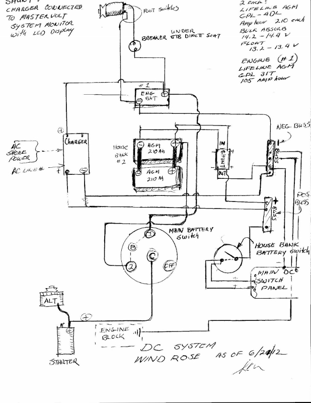
I've attached a basic schematic of my set-up. I've checked and rechecked it for accuracy. Any help will be much appreciated.
Thanks
Sam
Capt. Sam Murphy
1994 Catalina 36, Hull 1327
Shoal draft, two cabin model.
Panama City, Florida
Use an Echo Charger or ACR relay to charge the start battery. Feed the new alt directly to the house bank with proper fusing for the +alt wire within 7" of the bank. You may also want to add a "service disconnect switch" in the alt + feed.
If going with a Balmar 80A (I'd recommend larger as it would work less hard) then you will definitely want, at a minimum, to install an alternator temp sensor.
For only a little more money the MC-614 regulator gives a lot more options. You can always dial back a larger alternator in belt manager but you can never make a small alternator bigger. A 100, 110, 120A Balmar will last longer when run at 80A than an 80A will being asked for full output day in day out.
I've replaced two alts in the last four weeks killed by AGM's and over heating and have another one tomorrow on a HUGE Cummins engine also cooked by 1200Ah of battery bank.... Temp sensing for the alt is becoming very important..
-Maine Sail
https://www.marinehowto.com/
Sam,
Like these
Basic Battery Wiring Diagrams This is a very good basic primer for boat system wiring: [url]http://c34.org/bbs/index.php/topic,6604.0.html[/url] [added 9/21/11]
[added 1/31/2012] This is another very good basic primer for boat system wiring: The 1-2-B Switch by Maine Sail (brings together a lot of what this subject is all about)
[url]http://forums.catalina.sailboatowners.com/showthread.php?t=137615[/url]
Stu Jackson, C34IA Secretary, C34 #224, 1986, SR/FK, M25 engine, Rocna 10 (22#)
Thanks for the help guys. I'm learning more every day and I've vowed to not install the alternator and regulator that's sitting on my kitchen table until I think I know what I'm doing. But its like going back to school. But its a subject that I like learning about and surely need to know.
I'm not going to take the suggestion of upgrading to a 100+amp alternator because of the need to use a heavier belt and therefore upgrade pullies and also loose HP of which I don't have much to spare. I am starting to consider exchanging my huge House back batteries (2 ea, AGM 210 Ah, weighing 124lb each) for smaller as I think I could live with around 300 Ah comfortably.
So, back to the studies. And thanks for the help.
Sam
Capt. Sam Murphy
1994 Catalina 36, Hull 1327
Shoal draft, two cabin model.
Panama City, Florida
Sam, sometimes it can be intimidating, but if you stay with it and re-read what MS wrote and the links I provided, you start seeing the big picture. You diagram is very well drawn, so we don't need to deal with teaching you how to draw wiring diagrams! :)
I have a 100A alternator, but with wet cells, 390 AH nice sized house bank.
If you buy the MC-614 instead of the ARS you will have a MUCH btter control of your charging system. I have the older MC-612, same idea.
In order to avoid the belt issue, I use this:
Small Engine Mode - discussion with link to the picture of the toggle switch: [url]http://c34.org/bbs/index.php/topic,4454.msg27149.html#msg27149[/url]
It works just fine, and I still use the original 3/8" belt.
Seriously, you should consider MS's advice and go with the larger alternator, especially with your AGMs. If you don't, i believe you'll regret it.
Whatever you do, however, you NEED to get rid of the connection between the alternator and the starter solenoid, and make the 1-2-B switch a USE switch, not a "charging" switch. It's a much SAFER system 'cuz you can't blow alternator diodes.
Stu Jackson, C34IA Secretary, C34 #224, 1986, SR/FK, M25 engine, Rocna 10 (22#)
Alright Stu. Thanks much. I may end up being stubborn about the alternator selection, one reason being that's its bought and sitting on the table. Won't the issue be resolved if I down size the AGMs or even downsize and switch to wet cells as you have?
I've printed off all the other info you provided and I'm off to the boat to study and plan. And mostly today to manage the dock lines as TS Debby comes barreling up to the Northern Gulf were we reside on the St. Marks river.
Boat neighbors just called to say last high tide was almost over the dock. (non floating) and Next high at about 1530 is going to be worse. So armed with extra fenders, fried chicken and cold beer, I should have plenty of time to plan the project.
Thanks again,
Sam
Capt. Sam Murphy
1994 Catalina 36, Hull 1327
Shoal draft, two cabin model.
Panama City, Florida
Sam, it's all about battery acceptance.
AGMs can gulp up current and will tax even high output alternators. Wet cells are a tad less burdensome on the alternator.
For the given daily draw.
It doesn't matter how big your house bank is, it's how much you have to replenish once you start your engine.
Use 100 AH on a 200 AH bank, or the same 100 AH on a 600 AH bank. You still have to put it BACK in.
Then read the first paragraph again...;)
Stu Jackson, C34IA Secretary, C34 #224, 1986, SR/FK, M25 engine, Rocna 10 (22#)
[QUOTE=Capt. Sam;13577]Alright Stu. Thanks much. I may end up being stubborn about the alternator selection, one reason being that's its bought and sitting on the table. Won't the issue be resolved if I down size the AGMs or even downsize and switch to wet cells as you have?
I've printed off all the other info you provided and I'm off to the boat to study and plan. And mostly today to manage the dock lines as TS Debby comes barreling up to the Northern Gulf were we reside on the St. Marks river.
Boat neighbors just called to say last high tide was almost over the dock. (non floating) and Next high at about 1530 is going to be worse. So armed with extra fenders, fried chicken and cold beer, I should have plenty of time to plan the project.
Thanks again,
Sam[/QUOTE]
If you keep your AGM's be sure to add the Balmar alternator temp sensor.... I am heading off to an expensive power boat today which has fried its third factory 120A alternator. Boat has Odyssey AGM's... He needs external regulation and temp sensing....
If you want an idea of what AGM's will accept take a look at this video. These batteries took over 130A for well over an hour during the set up and testing of this alt..
[URL="http://www.youtube.com/watch?v=Z0ijfk0DMPk"]http://www.youtube.com/watch?v=Z0ijfk0DMPk[/URL]
-Maine Sail
https://www.marinehowto.com/
Sam,
Maine Sail is right. The Small Engine Mode link I provided says:
[I]Use the SMALL ENGINE MODE. This requires a toggle switch between [I][B]alternator heat sense quick connect spades on the regulator board[/B][/I]. Switch in one position lets the full power signal to the alternator. Other position is 50% of required output.[/I]
All the toggle switch does is a manual initiation of the alternator heat sensor. You could put them in series (i.e., install the toggle AND the sensor) and get the same results (manual AND automatic). I chose manual, but putting the alternator sensor on makes it automatic.
It's all in the regulator manual, available for download at [url]www.balmar.net[/url]
Stu Jackson, C34IA Secretary, C34 #224, 1986, SR/FK, M25 engine, Rocna 10 (22#)
[QUOTE=stu jackson c34;13591]Sam,
Maine Sail is right. The Small Engine Mode link I provided says:
[I]Use the SMALL ENGINE MODE. This requires a toggle switch between [I][B]alternator heat sense quick connect spades on the regulator board[/B][/I]. Switch in one position lets the full power signal to the alternator. Other position is 50% of required output.[/I]
All the toggle switch does is a manual initiation of the alternator heat sensor. You could put them in series (i.e., install the toggle AND the sensor) and get the same results (manual AND automatic). I chose manual, but putting the alternator sensor on makes it automatic.
It's all in the regulator manual, available for download at [url]www.balmar.net[/url][/QUOTE]
I much prefer to set up the field output to be limited in "belt manager" and allow the temp sensor to do what it is supposed to do only when it actually needs to. Small engine mode is a 50% cut in field output and may not be necessary unless you need an immediate boost in power. If you need the power boost I'd rather cut the field all together and get all the engine power available.
-Maine Sail
https://www.marinehowto.com/
In the link that is embedded in the earlier Small Engine Mode link I gave you, it shows my toggle switch.
It also says this:
[I][COLOR="Blue"]We installed the simpler Small Engine Mode switch on our regulator. We did not purchase an alternator temperature sensor. Jon Schneider noted that he installed the alternator temperature sensor which performs the same function but ONLY when the alternator gets "hot." He ALSO noted he used the amp Manager at 50%, [B]so: he's got his amp output DOWN to 50% and THEN his alternator cuts back to 50% of that! [/B]My concept is to get as MUCH out of my alternator as possible, but just lightly load it at first when starting up after draining the house bank down past 85% - like a night on the hook with the fridge running.[/COLOR][/I]
So, Sam, now that you know how it all works, even before you buy an external regulator, your boat, your choice. :):):)
Stu Jackson, C34IA Secretary, C34 #224, 1986, SR/FK, M25 engine, Rocna 10 (22#)
OK, I'm back from three days aboard, surviving TS Debby. I've never, ever seen it rain like that. Horizontal at 20 - 30 kts, non-stop for 24 hours or more. The little town where I'm docked got 23"!! Nice thing is that Wind Rose didn't leak much, but my fowlies sure did.
But I had lots of time to study all the info you both have provided. Thank you very much! I now fully understand the recommended wiring of the 1-2-both-off switch and will make the change to make it only a "Use Switch" as part of my general rewiring. I dove even further into the PO's wiring mods and finally understood the two 4 gauge cables that seem to vanish into places I couldn't see. I simply pulled really hard on them and they came out, unattaced to anything, apparently just left as part of original wire harness when the mods were made.
I've already got the regulator Temp switches for both the battery bank and the Alt., but Im not quiet following the need for the toggle. I'll study the links provided.
I also need to now order a ACR to convert to the "user switch" concept. Any recommendations on model, Make, would be appreciated.
Again, thanks guys. I really don't know what I would do without your help.
Sam
Capt. Sam Murphy
1994 Catalina 36, Hull 1327
Shoal draft, two cabin model.
Panama City, Florida
Sam, glad you survived. Instead of the ACR you might be better off with an echo charger. The toggle is on the ground line from my combiner to avoid overcharging the reserve bank when motoring for long periods. With the echo charger limiting the charge amperage to the reserve bank to 15A, you won't need one. The other toggle you mentioned is most likely the one for the Small Engine Mode. It overrides the alternator temperature sensor, so if your alternator isn't hot (yet?), but you want to decrease the load on the belt, you switch and the regulator simply pretends that the alternator is hot and drops the signal to 50%. Does that answer your question?
Stu Jackson, C34IA Secretary, C34 #224, 1986, SR/FK, M25 engine, Rocna 10 (22#)
[QUOTE=stu jackson c34;13617]Sam, glad you survived. Instead of the ACR you might be better off with an echo charger. [B]The toggle is on the ground line from my combiner to avoid overcharging the reserve bank when motoring for long periods. With the echo charger limiting the charge amperage to the reserve bank to 15A, you won't need one.[/B] [/QUOTE]
Stu,
I am shocked to hear you of all people spout this misinformation about an ACR.;) This is a misunderstanding and common myth that folks who know little about how electrical systems work, or how batteries charge, [I]feel[/I] about how an ACR works. What you stated above, about over charging a start battery, is not possible with an ACR. The only way for this to be possible if you are also over charging the house bank. You can not over charge the start bank with an ACR, or by combining them with the BOTH feature.
Here's an excellent example of why that myth is just that, a myth.
The old start battery on our boat was charged for 2800 engine hours, with a DUMB REGULATED alternator and 5 solid years of solar during a 5 year world cruise. Our friends Norm and Judy did this once in a lifetime cruise on our boat boat before we bought her.. The batteries were purchased at the beginning of the cruise were combined during charging with a Yandina combiner.
When we bought the boat the batteries had been used for five straight years 24/7 with over 98% of the time spent on the hook cruising. That is a LOT more abuse than most boaters do in a lifetime. for the average boater that is 28 years of engine use!!!!! Over charge? The battery banks still worked when we purchased the boat at year six. I retired the house bank but the start battery was still actually fairly healthy so I gave it to my brother for his Mako. It started his boat into the batteries 8th season before finally getting weak enough to be of concern.
That battery was combined every day for five straight years via either solar or the dumb regulated alternator.
The bottom line is that current simply flows where it is needed, batteries will take what they need when batteries are combined, and the voltage becomes equal among the new combined bank. Unless your charger, alternator or solar/wind system is pumping out an incorrect voltage for you bank you will not over charge using an ACR.
A few weeks ago I had a customer over to my shop and was talking to him about an ACR. He regurgitated the same myth you just did. I had two batteries on my bench for equalization and they were both at varying states of charge but both above 80% SOC.
I connected them in parallel and then turned on the charger. I then put my clamp meter on each battery and each battery was taking a different level of current. One battery was near full and was taking just 2 - 2.2A the other battery was taking about 11 - 11.3A. The"combined" bank, both batteries, were at 14.4V but each battery was taking only what it needed. He immediately understood, by seeing it, that the batteries take what they need and only what they need in current.
I see and measure this stuff on a daily basis.. Had a house bank a month ago of Odyssey AGM's taking 120A of charge current from the alt. That bank was combined with a much smaller Odyssey starting battery. It was taking about 1.4A of charge current... All batteries in parallel and the house bank getting 120A and the start getting 1.4A. You don' need an Echo to limit the current the batteries do that on their own..:)
That said I do have a switch in the neg leg of my ACR. I use it to turn off the ACR so I am not burning amps in "combined" mode when charging off solar and so all the current can flow to my house bank without any "phantom loads".
I will be installing a Sterling ProLatch R soon, which is an ACR with near zero draw when combined, and a very, very low standby current. Once I get to that I won't need the switch in the neg leg...
-Maine Sail
https://www.marinehowto.com/
Wow! who knew this was so complicated? So back to my question of which ACR to buy, Maine sail are you recommending the Sterling Prolatch?
And too I don't need a toggle on the ground line of the relay.
Thanks
Sam
Capt. Sam Murphy
1994 Catalina 36, Hull 1327
Shoal draft, two cabin model.
Panama City, Florida
I am chastened. :o
Interestingly enough, that's the way I use our system. Combiner off when not on the boat using solar to the house bank instead of plugged in to shorepower, combiner on when charging with shorepower (like at marinas for weekends) or the engine.
Stu Jackson, C34IA Secretary, C34 #224, 1986, SR/FK, M25 engine, Rocna 10 (22#)
Come on guys!! which ACR already? I've got orders to place!
Capt. Sam Murphy
1994 Catalina 36, Hull 1327
Shoal draft, two cabin model.
Panama City, Florida
[QUOTE=Capt. Sam;13639]Come on guys!! which ACR already? I've got orders to place![/QUOTE]
If you have now or plan to upgrade to solar then the ProLatch R would be my choice. If you have no plans for solar than the Blue Sea SI is a great value and I would go that route..... The Prolatch R is more money so unless you have solar then go with the Blue Sea SI..
-Maine Sail
https://www.marinehowto.com/
[QUOTE=Capt. Sam;13639]Come on guys!! which ACR already? I've got orders to place![/QUOTE]
With respect to the issue you are "drowning in", there was a very detailed, clear article about the wiring issue (with lots of diagrams) in the technical section of March 2012 Mainsheet, written by John Nixon (if I remember his name properly), a C34 owner. I found it quite helpful. The author as well recommended the Blue Seas ACR as well (which I just installed).
Matthew Chachère
s/v ¡Que Chévere!
(Formerly 1985 C36 MKI #466 tall rig fin keel M25)
2006 Catalina Morgan 440 #30.
Homeported in eastern Long Island, NY
Matthew, glad you enjoyed and remembered John's article in Mainsheet. He is our Technical Editor. The issues John discussed were covered in our previous links to Sam. Gosh, I should have remembered Johns article, but didn't. We have a "backlog" of Tech Notes that we usually post on our website for C34IA members access, much like you folks have member-only access. We'll get to it soon.
Question is, which model ACR did you use?
Stu Jackson, C34IA Secretary, C34 #224, 1986, SR/FK, M25 engine, Rocna 10 (22#)
[QUOTE=stu jackson c34;13649]Question is, which model ACR did you use?[/QUOTE]
The Blue Seas SI series (start isolation) , p/n 7610.
Amazon has them for about $75, including shipping.
Haven't had it long enough to recommend it one way or the other, but seems to get good reviews from others on this site and others...
Matthew Chachère
s/v ¡Que Chévere!
(Formerly 1985 C36 MKI #466 tall rig fin keel M25)
2006 Catalina Morgan 440 #30.
Homeported in eastern Long Island, NY
Ok, then. Thanks Matthew and Maine Sail. The Blue Sea SI it is. Although Defender's price is up to 79.99. But what's money to a sailboat owner, whoopee!!
And, I've got to order at least 24 feet of 1/0 tinned cable with lugs. That's another$135 or so with shipping. I'm hoping to keep this whole re-wire project, with new Alt, Reg and ACR to under a thou. but its getting close.
And THEN I'll order the new fridge at $1,600. All this for a cold beer.
But now that I think about it, I've got about 50 feet of old #4 cable that the PO left going to no where. I'll make anybody a good deal on it! 11ft of red and about 35 ft or so of black.
Capt. Sam Murphy
1994 Catalina 36, Hull 1327
Shoal draft, two cabin model.
Panama City, Florida
Here's the new schematic proposed for Wind Rose with the 1-2-all switch wired to be a "Use" only switch and the new ACR wired in correctly I hope. And the PO's old "house" switch eliminated. The 24 feet of new 1/0 is 12 of red and 12 of black, to make the connections direct from the Alt to the house bank and neg. buss.
If anyone takes the time to look at this and tell me there's a problem before I Blow her up, I'd be eternally grateful. (and to Stu and Maine Sail, there's no toggles in it yet. But I might add one later if I get comfortable with the idea.
Thanks
Sam
Capt. Sam Murphy
1994 Catalina 36, Hull 1327
Shoal draft, two cabin model.
Panama City, Florida
Sam,
Good morning, nice job (are you an illustrator?:))
1. Charger output options - you have two ways to do it: One or two connected to banks: 1) dual outputs: what you show is OK (if you remove the + shunt (see #3 below); 2) Use just a single output of the charger to the house bank (PDP), just like your AO going to the house bank (HB). Option 1 usually works well. Your charger will be feeding the house bank since the reserve bank is almost always full anyway, [U]just like the AO[/U]. Check to see in your manual that your charger will do full output if only one output is used.
2. Bus bars: You have four wires each on the + posts of your battery banks. You want to minimize the number of wires on the physical posts. That's what the bus bars are for. Arrange the bus bars and wiring so the wiring goes from the loads/charging sources to the bus bars with only one wire to the battery bank(s). The bus bars become the PDP and NDP of your system. Consider renaming the "DC Positive Bus" to "House Bank PDP." With all the wires going to the reserve bank + post, consider buying another bus bar or a Power Post for a "Reserve Bank PDP."
3. Shunt & NDP/PDP: If it's for a battery monitor for the house bank, only the negatives get wired to a shunt. Battery to shunt (battery side of shunt) with only ONE wire, shunt to bus bar (the NDP) from the load side of the shunt, all other house bank negatives (loads) connect to the NDP, with one wire from the NDP back to the engine ground (per Maine Sail's battery monitor article: How to Wire a Battery Monitor by Maine Sail: [url]http://forums.catalina.sailboatowners.com/showthread.php?t=125606[/url]). One wire goes from the house bank + to the PDP directly and then to the switch, with the AO and charger input wired to the HB PDP, no shunt involved.
4. It appears that you've X-ed out the wire from the + post of the house bank to switch position #2, and run the + from the HB PDP to the switch. That's right. Since it appears from your notes at the bottom that you're removing the existing wire from the HB to the switch, unless it's undersized, then just move it from the house bank + post end to the HB PDP if you physically can instead of removing it.
5. Alternator ground - Depending on the physical location of your NDP, you may not need to run that ground all the way back to the NDP, just connect the alternator ground to the same spot on the engine that your NDP goes to.
6. Many of us use 1 for the house bank and 2 for the reserve bank. Not really an issue, but my switch goes off, 1, both 2 - it's not completely rotary, so I never go through both to connect my house bank. It's a "convention" only in that in the old days the Link 2000 needed to have the house bank as #1 for programming purposes. As Maine Sail wrote, #1 is used almost all the time, so #2 "comes later" and easy to remember. Just change the 1 and 2 on your switch. In fact, that's the direction my switch goes in when facing it anyway, maybe yours, too. That'll eliminate a redraw.
7. Bus bars - You may not find a 5 post bus bar, most come in four or more, so just drop two wires on one of the posts. You can do this with big wires as well as smaller ones like the stereo memory and the bilge pump.
8. Don't forget to show the fuses.
9. MS and I both recommend a simple on/off switch in the AO to the PDP. This allows you to work on the alternator without becoming a sparky. I haven't yet installed mine and disconnect the fuse before I do any work. He calls his a "Service Switch", I'll call mine "AO Disconnect" but you MUST be sure to turn it on before you start your engine.
10. Regulator: If you're installing one, make sure the battery sense wire goes to the house battery, the HB PDP or at least to the #1 house bank post on the switch (different end of same wire). Also the temperature sensor mentioned by Maine Sail earlier in this thread.
Stu
Stu Jackson, C34IA Secretary, C34 #224, 1986, SR/FK, M25 engine, Rocna 10 (22#)
Stu, Wow! that is more help than I expected or deserve. You're the greatist!
I see your point clearly on the stacking up cables on the battery post issue and I will correct that as you recommend. (actually there's only three on the HB post, one is removed (x-ed out) but I can see that's two too many.
And much appreciate the recommendation to only run the Alt. Neg ground back to the engine block. That's about $50 less cable than I'd planned. (MEMBERSHIP IN C36IA PAYS!!)
I will add fuses to the diagram. There are fuses on the PDP for the line from charger and line to existing bat. switch. I'll use another on the line from the AO. I'm assuming that any power-in line coming to RB or HB should be fused. I'm ordering a 125 amp fuse for the AO at PDP? or should it be more, 150??
As to the wiring of the Shunt. This unit is a MasterVolt Master Shut 500, installed by the PO's electrician, whom I have spoken with. He said he was unfamilure with the device prior to this job, and wouldn't have used it but the PO insisted. The Electrician said he relyed heavily on calls to the U.S. distributor during the installation. Note the attached diagrams from the MasterVolt manual. Its connected by data cable to the MasterVolt charger and the LCD display.
I read this that I have to have the positive from the HB in and then out to the PDP. See attached.
The MasterVolt company is in the Neatherlands and the manual I have is a minimal affair and the English translation is not the best. So I'm struggling to learn how to use its many features. But I'm thinking its probably wired correctly and I'm loath to change it for now.
So, I'm busy making the changes as you recommend and again, Stu, Thank you very, very much.
Sam
Capt. Sam Murphy
1994 Catalina 36, Hull 1327
Shoal draft, two cabin model.
Panama City, Florida
Sam, given the catalog information what you've shown looks right. Glad to help. Good luck.
Stu Jackson, C34IA Secretary, C34 #224, 1986, SR/FK, M25 engine, Rocna 10 (22#)
Sam, here's my 1-2B switch
Stu Jackson, C34IA Secretary, C34 #224, 1986, SR/FK, M25 engine, Rocna 10 (22#)
OK, here is the new and improved version of Wind Rose's wiring, incorporating most of the wise suggestions from Stu and MS. I'm done ( I hope) drawing schematics and off to the boat to deal with the tangibles.
One last question Stu, I'm going to do as you suggest and connect the Alt neg post to the engine ground where the heavy black cable from the NDP attaches to the block. But don't I need to be sure that that existing cable is sufficient (i.e. size 1/0 for 12ft run with 80+amps) and if not replace it?
Anyway, that's the plan.
Thanks again for all the great help.
Sam
Cancel that last question. The cable going from the negative buss (NDP) to the Engine ground point is 1/0 awg as recommended by the charts I've read. So, I'll just run another short 1/0 from the alt. to the eng. ground point.
Capt. Sam Murphy
1994 Catalina 36, Hull 1327
Shoal draft, two cabin model.
Panama City, Florida
Just a final update; the job is DONE! All wired in accordance with the schematic and incorporating most of the great recommendations from Maine Sail and Stu Jackson. New 80 amp Balmar Alt., with ASR-5 reg. New ACR, and main battery switch now wired as a "Use only". Cranked up the engine yesterday and all worked great. Taking a longer cruise soon to monitor battery charging. Still have some things to learn about Alt. load management and programing that new Regulator with the magnet.
Always learning! Thanks MS and Stu.
Sam
Capt. Sam Murphy
1994 Catalina 36, Hull 1327
Shoal draft, two cabin model.
Panama City, Florida
Great news. All the best, Stu
Stu Jackson, C34IA Secretary, C34 #224, 1986, SR/FK, M25 engine, Rocna 10 (22#)
I'm in the process of doing a similar upgrade, and have a question about what to use as the length to determine the size of wires to use. My plan is to run the AO to he house bank positive bus bar, and the alternator ground to my engine ground .
It's a ~16 foot run from my alternator to both my positive (and negative) bus bars, and about 1 foot from the alternator ground to the engine ground. So, can I use ~17 feet as my round trip, or should I be using 32 feet? 32 feet would push me to 1awg wire (versus 4awg for a 17foot run) we have he 90 amp Leece Neville alt.
Thanks
Sent from my iPad using Tapatalk HD
Alex & Caitlin
S/V Windswept
Vancouver, BC
1985 C-36
SR/FK M25
Alex,
For determining wire sizes, you should use the round-trip distance. In your case that is 32'. #1AWG sounds about right from memory. You definitely don't want #4 with a 90A alternator. Hope this helps.
Tom Sokoloski
C36/375IA Past Commodore
Noank, CT
Thanks Tom,
That certainly clears that up. I'll run the 1 awg from the AO to the positive bus bar, then 1 awg from the engine block to the negative bus bar (if it's not already 1 awg), then 1 awg from the alternator ground to the engine block.
I am now a little concerned about the required sizing of the ground wire from my negative buss to the engine block, what is the rule on this? (I've searched the forums, and can't haven't found a definitive answer). My concern is the 1 awg can handle the 90 amps from the alternator, but what happens when I throw my windlass into the mix? Assuming both are operating at their max input/output, I'd have 90 amps from the alternator, and the 80amps from the windlass. Then we're at 170 amps. All the other wires are/will be the appropriate size to handle this, but we don't want the ground -> engine block to be the weak link in my system.
Thanks,
Alex
Alex & Caitlin
S/V Windswept
Vancouver, BC
1985 C-36
SR/FK M25
I think your windlass ought to be on an isolated circuit, not connected to the eng. ground. Mine is that way, and i thought that's the way it was done by the factory. Windlass is isolated on its on circuit feeding only off the eng reserve battery with its own circuit breaker. I always run the engine when the windlass is in use, so no risk of depleating the reserve bat.
sam
Capt. Sam Murphy
1994 Catalina 36, Hull 1327
Shoal draft, two cabin model.
Panama City, Florida