

Hello All,
I’ve been stumped by my alternator not putting out current. I would like your help in diagnosing this.
We recently did a full upgrade of our electrical system based on reading these posts, especially those from Maine Sail and others (thank you!!!!!). Below is background/preamble to the main alternator problem I’ll be asking below:
- Purchased a new alternator/external regulator from compass marine but have not installed it pending a future alignment project (the new alternator is proud by 9mm from the main crank and raw water pump pullies.
- Rewired old alternator (Prestolite/Leece Neville 51 A) directly to our main battery bank (older flooded lead acid to be upgraded to AGM in the future) rather than through starter and 1-2-both-off switch using 2/0 cable. we also installed an alternator service disconnect switch in engine compartment.
- Installed a heavy 2/0 negative cable from alternator negative post to a new negative bus bar in engine compartment. This bus bar connects to the main battery bank negative and to the ear of the starter. This new cable from the alternator negative post to the negative bus bar was mainly for our new (yet to be installed) alternator because our old/current alternator never had this cable (presumably it is case-grounded).
- Used all new 2/0 cable between alternator and batteries and from batteries to 1-2-both-off to starter.
- Battery positve now connects to a positive bus bar which distributes power to: ACR, 1-2-both-off switch at panel, alternator positive, AC charger, solar controller and ALL are fused with MRBF fuses (nothing previous was fused and all previous wires to these destinations were undersized/corroded!!!). Using two neat MRBF fuse bus bars that are connected to each other.
- Upgraded our AC charger to a new one.
- Installed an ACR to regulate charging the main bank and emergency batteries
- Installed a new 1-2-both-off switch
- Installed a Balmar battery monitor
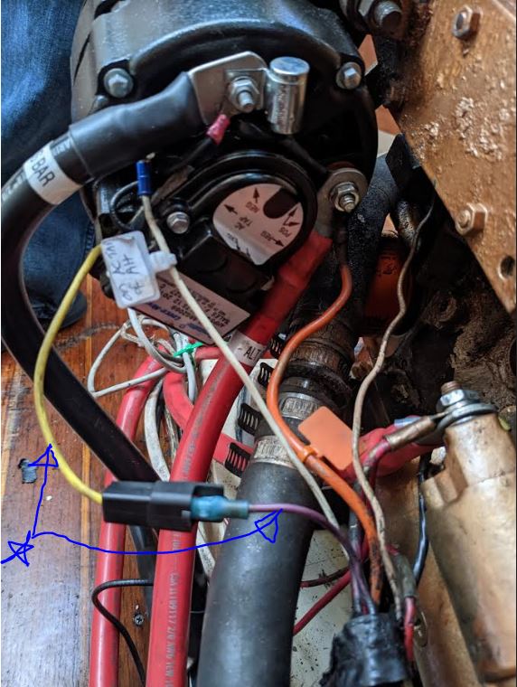
Now here’s the problem. Our alternator does not seem to be charging the batteries at all. I checked DC amps with a clamp-on DC multimeter and it is not putting out any current even when the batteries are discharged (whether at idle or 3000 rpm). I took off the alternator and took it to a reputable shop and they tested and said it was OK. They said the problem may be with the yellow wire that comes out of the alternator regulator (on the back of the alternator). A few months before this upgrade, I noticed the yellow wire was disconnected. I also noticed a purplish wire coming from the ignition harness that was not connected to anything and which was missing any kind of terminal connection (just a bare wire). I assumed this was the previously connected to the yellow wire from the alternator I connected the two wires after seeing pictures online that show them connected. When I disconnected them I lost my tachometer readings. When I connected them I regained my tachometer readings so I assumed that the yellow wire and purple wire were properly mated and so labeled the yellow wire coming out of the regulator with a “tach” label. Upon taking the alternator to the shop, the gentleman said that the yellow wire was NOT the tach wire, but rather the excite wire for the alternator. He said that the alternator was not putting out amps to the battery because the regulator was not receiving the excitation current.
Based on this narrative and the picture below (the yellow and purple wires in question are indicated with the blue arrows), is the shop guy correct? If he’s correct, where should I connect the yellow wire from the alternator to get an excitation current? If he’s correct, what is up with the purplish wire and should it be connected to anything at all? I would be thrilled to get the alternator to put out current to charge the batteries. Your help would be greatly appreciated. Sorry for the long narrative, but I’m trying to be as complete as I can.
Cheers,
Adel
Sounds like our upgrades -- which we did over 10 years, however, not all at once, so good for you!
We replaced the stock alternator just last fall (when it began failing) with a Compass Marine 105 amp alternator (derated via an external regulator), happily there were no alignment issues so it was a drop in replacement.
Anyway, I had some initial issues with the wiring for the new alternator (all the gauges went nuts), and had to go back to basics and try to sketch out a "before" and "after" to figure it out. I've pasted the sketches below. As I'm not at the boat right now (its snugged away under its winter cover and a bunch of snow), my response is somewhat from memory.
But, in any event, with the old alternator and the original wiring (well, there had been the upgrade at some point by a prior owner from the "trailer plug" and ammeter setup on the early Mk1s like ours), there were three cables. One was the heavy cable from the positive terminal that fed the batteries (and originally connected directly to the starter positive post as well), one was a small wire from the stator that ran to the tachometer, and one was a small wire that ran from the field (or "excite") to the key switch at the engine panel (the negative connection was via the case ground). My sketches don't relate the correct colors, but if I'm remembering correctly the purple wire is the wire that carries the current from the key switch to the field of the alternator, and a grey wire is the connection for the tachometer to the stator post on the alternator. In any event, I suggest tracing the two relevant wires from the back of the engine panel (i.e., the output side of the key switch and the tach connection) forward to the engine so you can figure out which is which.
Mainesail's "How To" pages at Compassmarine has a picture of the wiring on the alternator here: https://marinehowto.com/wp-content/uploads/2016/04/03-Universal-Diesel-Wiring-Harness-Upgrade.jpg
Matthew Chachère
s/v ¡Que Chévere!
(Formerly 1985 C36 MKI #466 tall rig fin keel M25)
2006 Catalina Morgan 440 #30.
Homeported in eastern Long Island, NY
Thank you for your help, Matthew! I think I have those drawing but am just not sure which wire is the one that excites the alternator. In your first diagram (your old system), it looks like the blue wire that connects to the ignition does this excitation. I will trace my wires when I get a chance to find out which wire from the ignition connects to the excite wire on the alternator.
Adel
Problem solved. I had not seated the MRBF fuse properly on the fuse bus bar!! There was an open circuit. All is well. Alternator now puts out 55A when engine starts and we rev up to 2000rpm. It was good luck that the alternator did not blow out its diodes upon starting since it did not have anywhere to dump its load. Thank you all for your combined wisdom. Now to change out the solar wires and controller.
Adel