
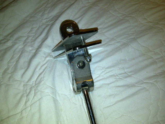
We recently posted our initial ideas for a new chain plate design on the C34 and C36 websites. As expected we got great feedback. We have progressed to producing the chain plates which we will be installing next weekend. (See image). The main features of the updated chain plate design are: 1) A deck plate portion that is welded to the vertical shroud bar part of the chain plate that will not allow any water seepage. The deck plate also accommodates the deck bolts which increases the surface area for sealant and for compression of the deck plate against the deck. 2) A similar sized backing plate to sandwich the deck between the deck and backing plates. 3) A full sized articulating toggle to connect the shroud bar to the tie rod.
When installed, the new chain plate design will accomplish two essential goals: 1) A seal to eliminate water ingress into the slot-shaped hole in the deck which could ultimately compromise the deck core. (This is what we are all trying to avoid. 2) The ability to tension the tie rods beyond what is currently done out of the factory which just beyond hand tight. This will tension the triangle formed by the tie rod, outer hull, and deck and result in a stiffer hull. Under sailing conditions this will decrease the relative movement between the chain plate and the deck which will further preserve the integrity of the seal between the deck plate and the deck itself ultimately decreasing the chance of water ingress.
All else aside we think the new design will look great and will be a real conversation piece with other C34 and C36 owners.
Tony Germin
1997 C34 #1331
Rick Verbeek
1999 C36 #1763
Lakeshore Yacht Club
Toronto, Ontario
Rick Verbeek
Southpaws
1999 C36 #1763
Lakeshore Yacht Club
Toronto
That looks pretty darned good! I hope to hear positive comments from you after the summer trials!
Tom & Janis Grover
C36 #0949
SR/WK, M25XP
Midland, ON
Tony and Rick,
Normally I don't hesitate to comment on things regarding engineering, but I am refraining because this is an area I don't feel competent to discuss intelligently at this time.
Nevertheless, I want to compliment you on your thoughtfulness and considered approach to the problem. Best of luck.
Duane Ising - Past Commodore (2011-2012)
s/v Diva Di
1999 Catalina 36 Hull #1777
Std rig; wing keel, M35B, Delta (45#)
Punta Gorda, FL
http://www.sailblogs.com/member/diva-di/
Tony and Rick,
Nice design, it should improve the seal at this junction.
We do have fairly flexy boats, the original design does indeed allow the deck to move independently from the hull. This in fact creates the issue of the need to occasionally rebed this area.
As you state the unit you have designed will stiffen this junction. My question would be what does Mr. Douglas think of this, with the deck unable to float, could this create unforeseen load issues.
Cepheus dream
C36 MK I # 825
MK I Tech Editor No Mas
I'm no engineer, but it seems to me that if the tie rods are tightened snugly can the deck really move in that area regardless of whether using the original chainplates or these re-designed ones? Aren't the loads all carried through to the structure were the tie rods terminate in the hull? The load is all up isn't it? You can't push through a wire. I've never seen any deck movement in either this boat or the 28 we had, but then again we're not gonzo sailors either. Perhaps we're talking movement in the 32nds of a inch range which would not be noticeable to the eye?
One other comment I would make is that this is the same design as the 28 and they too will eventually leak. I like that design a lot but, it was a bear to pull them and re-bed them whereas the little cover plates on the 36 are pretty easy to remove and rebed without even taking the shroud off. Which is good since they seem to need that a fair bit!
Bud,
Our chainplates are sealed where they go through the deck and the metal cap is not bonded to the shroud but, is mearly a cover to keep the sealant from breaking down too quickly. The design wether by purpose or not would allow the deck to move independantly from the shroud. Again I do not know if this is by design or just the cheapest way to do it.
Pounding in a seaway are boats flex a fair amount, there are post here adressing issues of cabin windows leaking do the cabin flexing in rough conditions. I like the design of Tony and Ricks chainplate seal but, my background in aircraft repair suggest serious thought be given to a repair as there are times when you can beef up one area only to transmit the load to a weaker area not designed for the load. My last boat had a boot at the mast and the mast would float around in the opening in the cabin roof. The previous owner had driven wooden wedges in around the mast to keep it from moving thinking he was making it stronger. The result was a sizable crack in the cabin top that was not disigned for the load. I replaced the wedges with a foam seal that allowed movement and kept water out.
The design looks robust and may certainly reduce the time between rebeding this joint. It too will likely strengthen the area, I would just like to know if the original installation was designed to allow movement at this location for a reason. Mr. Douglas if your out there please feel free to chime in.
Cepheus dream
C36 MK I # 825
MK I Tech Editor No Mas
Steve:
Great comments. No doubt loading the deck by tensioning the tie rods will stiffen the area between the forward chain plates and the aft chain plates on especially the C34. On the C36 this area is already stiffened by the bulkhead. Nevertheless, any additional tie rod tension will still be constant and locally distributed. Two places that come to mind are the deck to hull joint and the fiberglass structure in the salon area where tie rod is bolted to the aluminum "L" beam.
However, similar stresses occur in these areas in the original design secondary to flexing of the hull under a load except in this case, stresses would be periodic and occur in spikes. Either way the deck to hull joint structure should be strong enough to accept this load. One might suggest that the ability to tolerate “stress” from a constant load is optimal compared to periodic spikes. Less flexing of the deck with the new design will also mitigate upward motion of the chain plate relative to the deck resulting in decreased stress on the weld between the deck plate and the shroud bar parts of the chain plate.
My plan is to compress the deck in the area of the tie rods by no more than 1/8 of an inch which will be measured using a dial gauge. The torque required to achieve this will also be measured which I suspect will be somewhere between 10 to 20 ft-lbs. The aim is to have the pre-set downward tension on the deck exerted by tie rods/new chain plates sufficient to minimize relative movement between the chain plate and the deck when the shrouds are tensioned under resting conditions and undergo changes in tension during sailing conditions.
Ultimately, the resting tension will be greater on these new chain plates but the stress exerted on the hull/deck should be well below what occurs under expected sailing conditions in the original design.
Tony Germin
1997 C34 #1331
Lakeshore Yacht Club
Toronto Ontario
Rick Verbeek
Southpaws
1999 C36 #1763
Lakeshore Yacht Club
Toronto
I was searching the forum for lower shroud chainplate tie rod nut torque and came across this post. I've replaced my lower shroud chainplates with the original design and wanted to know what the torque of the tie rod nuts is. I've read here that its just past hand tight and another post mentioned "snug". Does anyone have a more definitive answer to the torque of the tie rod nuts? Thanks
Cuba-
The suggested chainplate tie rod torque, as "snug", is the same as the recommended torque for the turnbuckle connecting the cabin roof to the mast. "Snug" applies a minimal load (virtually "0")when the boat is at rest, acting like a solid piece of metal. Torquing and applying a load while the boat is at rest in both these areas accomplishes no benefit in my mind. It adds unnecessary stress/load to the metal components and deck......Just my opinion.
Paul & Wendy Keyser
"First Light"
Rye NH
2005 C36 MKII #2257
Wing, M35B
Thank you. That makes sense. As a ex fighter jet crew chief, snug was never going pass the inspection LOL.
Cuba-
Thanks for service! In some previous work, I supported C-17 and C-130 maintenance. I agree. "Snug tight" would never work on an aircraft.
Paul & Wendy Keyser
"First Light"
Rye NH
2005 C36 MKII #2257
Wing, M35B
Thanks! Enjoyed my 25 years in the Air Force.
I believe the weakness of your new designed Chain Plates is the deck portion of the load is being transmitted through the Two (2) bolts to the backing plate. If you think in terms of half the load should be to the deck and half should be thru the tie rods, you have introduced the bolt threads into the equation. You do not want bolts to be in tension where the threads are taking the load, bolts should always be in shear,
One solution to this problem is to extend the tang which goes thru the deck, connecting to the tie rod, and drill a hole thru to except a modified 1/2" inch clevis pin. The head of the clevis pin needs to be ground flat so the pin can be inserted in the hole snug against the backing plate. I think the bolts will allow enough pressure on the deck to compress it enough to allow some tolerance with the location of this hole. The extension of the tang to the tie rod would probably require the tie rods to be shortened. But this design would be as strong as the original design.
I hope I have provided enough information here to warrant a response.
Clifford Bassett
s/v " Red Dog "
1984 C-36 Hull # 260
M25 SR/FK
Holland, Michigan