

Hi there,
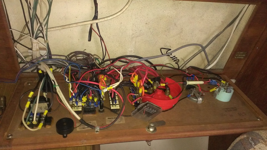
One of the winter projects I have taken on is the re-wiring of the electric panel. My question would be about the wiring scematic found at this [URL="http://c34.org/bbs/index.php?action=dlattach;topic=6604.0;attach=3024;image"]link[/URL] does this make sense for our boats? If this is not the way to go does anyone have a suggestion? I have included a picture of the panel.....the modifications I guess were done by the previous owner>? or was this the way they came off the assembly line from Catalina?
—
Larry Robcke
MKl Tech Editor S/V L' Amante #319, 1984 C36
Sailing Long Island sound and the Hudson River
Hi Larry,
I'm doing the exact same thing (using the same schematic). My big concern was finding somewhere to put all the new large bus bars and fuse blocks. Otherwise, the setup shown in that schematic does make sense and works (at least so far in my boat... I'm about 90% rewired using that schema). I've got the mkII, so the battery switch is separate from the rest of the panel (which makes it much cleaner than the setup you've got), but otherwise it should work for you as well.
-J
Josh McElwee
Sailing from East Greenwich, RI
2000 C36 MKII, M35B, "Chinook", Hull#1900
[QUOTE=2sailaway;16619]Hi there,
or was this the way they came off the assembly line from Catalina?[/QUOTE]
Larry, absolutely not. The OEM design should be included in your owners manual, available on this site.
That diagram in your link is one I found on sailnet and posted on our C34 "Electrical 101" topic. [url]http://c34.org/bbs/index.php/topic,6604.0.html[/url] It is far superior to the OEM wiring in that the alternator output is run directly to the house bank. It uses an ACR to automatically charge the reserve bank. ACRs were not included in the OEM wiring either. You can use an echo charger in lieu of the ACR (or a combiner, if you choose).
I heartedly endorse it.
Stu Jackson, C34IA Secretary, C34 #224, 1986, SR/FK, M25 engine, Rocna 10 (22#)
[QUOTE=jmcelwee;16627]Hi Larry,
I'm doing the exact same thing (using the same schematic). My big concern was finding somewhere to put all the new large bus bars and fuse blocks. Otherwise, the setup shown in that schematic does make sense and works (at least so far in my boat... I'm about 90% rewired using that schema). I've got the mkII, so the battery switch is separate from the rest of the panel (which makes it much cleaner than the setup you've got), but otherwise it should work for you as well.
-J[/QUOTE]
What I am doing for the large bus bars is mounting them in the big white space behind the wires, I have made a 15x30 board that will mount in that space. I have epoxied 1/2 screw strips directly to the hull and will fasten my board to them. I will post pictures once that is in place.
Larry Robcke
MKl Tech Editor S/V L' Amante #319, 1984 C36
Sailing Long Island sound and the Hudson River
[QUOTE=2sailaway;16619]Hi there,
One of the winter projects I have taken on is the re-wiring of the electric panel. My question would be about the wiring scematic found at this [URL="http://c34.org/bbs/index.php?action=dlattach;topic=6604.0;attach=3024;image"]link[/URL] does this make sense for our boats? If this is not the way to go does anyone have a suggestion? I have included a picture of the panel.....the modifications I guess were done by the previous owner>? or was this the way they came off the assembly line from Catalina?[/QUOTE]
That diagram would be fine however if you have the same size wire for the ACR as you do the main battery bank cables then the fuses on the banks are already sized for the ACR wire. The solar panel fuse should be on the bus bar side of the controller.
-Maine Sail
https://www.marinehowto.com/
I rewired last year. On first inspection I planned on using the the existing wiring harness and layout. It did not take long to figure out the existing wiring is too small and not to any standard. Solution, cut it all out and redesign from scratch. Ther is no need to worry about where a wire went. :D I know what I have and where it goes, as things are added new lines are pulled in, not spliced into the most convinient power source...
I also built a new panel, lots of breakers, easy access to behind the panels and mounted buss bars and other components on plywood panels secures to the hull. I should take a picture of these but yet another winter storm is blasting up the NE coast. Tarps are secure and maybe can get there in March... Attached is a pic of the pannel as it was being installed in the spring.
Ross & Joanne
Wavelength
Saint John NB
RKYC
C36 #658 TR 1987
[QUOTE=Wavelength;16640]I rewired last year. On first inspection I planned on using the the existing wiring harness and layout. It did not take long to figure out the existing wiring is too small and not to any standard. Solution, cut it all out and redesign from scratch. Ther is no need to worry about where a wire went. :D I know what I have and where it goes, as things are added new lines are pulled in, not spliced into the most convinient power source...
I also built a new panel, lots of breakers, easy access to behind the panels and mounted buss bars and other components on plywood panels secures to the hull. I should take a picture of these but yet another winter storm is blasting up the NE coast. Tarps are secure and maybe can get there in March... Attached is a pic of the pannel as it was being installed in the spring.[/QUOTE]
That panel is a thing of beauty...for me the wiring is the first step I will work on the panel next winter. one question for you, it looks to me that you made the panel access a bit bigger but used the existing hinges. Did you do the work yourself? As for the panels did you wire those yourself as well or order them ready made from someone like Blue Seas? It also appears that the section with the electronic comes out at a bit of an angle, did this allow for the proper clearance in the back? I would love to see the pictures of the busbar fi you get a chance.
Larry Robcke
MKl Tech Editor S/V L' Amante #319, 1984 C36
Sailing Long Island sound and the Hudson River
I took the original panel and reused the frame parts and made a few pieces to match. The panel was one I purchased on Ebay and rebuilt as well. It unfortuately still has a couple of glitches in the meters, I may repplace them with analog ones. Yes the panel angles out, it allowed for some extra depth but also made for better viewing in the nav area. Looks neat too. :).
I have been a cabinet maker for the past 30 years and spend a lot of time working on boats... This is my part time job for the fun of it. Real job is teaching High School Shop... Good Pay and have the summer off. That is important for sailing here in Canada.:D
If next week is warm enough.... I will see if I can get some pics of the interior wiring and busbars.
Here is a pic of the panel frameunder construction.
Ross & Joanne
Wavelength
Saint John NB
RKYC
C36 #658 TR 1987
Well I am almost finished, I have to say everything works well and the lights are steady and bright now also. The Blue Sea MaxiBus bars with covers are very nice indeed. This whole setup cost me a little over $300 with the new connectors, heat shrink and battery terminals but is worth every penny in piece of mind. I know exactly what and where everything is/goes. The pictures below are before and after shots. All that is left to do is a couple of inline fuses and to reinstall the wood portion of the panel and tie things nice and tidy with zip ties. Once the project is completed I will post the final pictures.
Thank you all for the advise and recommendations.
Larry Robcke
MKl Tech Editor S/V L' Amante #319, 1984 C36
Sailing Long Island sound and the Hudson River
Larry -
Looks very nice -- your "before" picture looks like our wiring mess at the moment, alas. Two thoughts:
1) I see you have the same Blue Seas battery combiner we have. I originally started to install it in the same location last year (i.e., behind the panel) and in a similar manner, but the instructions ([url]http://assets.bluesea.com/files/resources/instructions/990170140.pdf[/url]) state "It is recommended that the ACR be connected directly to your battery positive terminals through appropriately sized fuses. Connecting in a different location such as a battery switch may affect accuracy because of voltage drop along current carrying conductors." Apparently, any voltage drop can cause cycling (see [url]http://www.bluesea.com/articles/527[/url]). So it ended up installed in the battery compartment with direct connections to the positive terminals.
2) My understanding is that one of the weakest points of the original panel setup is the use of a daisy chain of small connections to supply power to the fuses and switches that make up the branch circuits -- which your pictures shows you still have. Replacing these with two small bus bars might be in order (not that I've gotten around to doing it on our boat, but its on the endless list somewhere....)
Matthew Chachère
s/v ¡Que Chévere!
(Formerly 1985 C36 MKI #466 tall rig fin keel M25)
2006 Catalina Morgan 440 #30.
Homeported in eastern Long Island, NY
I've been looking at my electrical panel. It is not as bad as some that I have seen, but not really what I want to see when I open that panel. My boat like many has suffered through previous owners adding stuff and running wires however they see fit, or removing stuff and leaving the wiring intact (some things like my VHF radio (there is only one) has three power cables run to it). I'd like to clean this up this winter, and I know many have done this project. I'd like to see the results of your work so I can copy some of it and not re-invent the wheel.
Greg Perkins
Port Orchard, WA
1986 Catalina 36
Sail #528
[quote=GregoryDPerkins] I'd like to see the results of your work so I can copy some of it and not re-invent the wheel.[/quote]
I'll be at the Catalina Gathering at Roach next month if you want to see a ad for BlueSea products ( the PO is the VP product development engineering there). If not I'm sure we could find a weekend your on this side to show off my baby.. (touching is better than pictures).
Les
Les & Trish Troyer
Mahalo
Everett, WA
1983 C-36 Hull #0094
C-36 MK 1 Technical Editor.
Commodore
Larry, I love how look the organization of your electrical panel, how tick is the board you have in the back to connect all your bus bars, what type of material is it?
Ludovic François
Hotel Catalina - Catalina 36 Hull #883
Marina Del Rey, CA
Larry - I'm not a fan of A/B/Both switches - there is a good discussion on the merits/problems on this thread of sailboatowners - https://forums.sailboatowners.com/index.php?threads/1-both-2-off-switches-thoughts-musings.137615/ it is rather long - I have two on/off switches which connect the starter battery to the starter and one from the house bank to the starter, I also have a 120A CB which feeds my main DC panel, and a 30A MRBF that feeds a separate 24x7 fuse panel (for VSM or Battery monitoring, bilge pumps..) I've attached a block diagram showing major portions - I worked all Friday night and Saturday on installing a new charger and the MRBF/ANL fuses shown - I still have some work to go - I need to rotate the batteries under the Nav Seat 90 degrees, add more fuses the other batteries and fuse the alternator.
Les & Trish Troyer
Mahalo
Everett, WA
1983 C-36 Hull #0094
C-36 MK 1 Technical Editor.
Commodore
Les,
Your drawing shows only two battery switches with a jumper between them (Beneteau/Jenneau style). With both switches in the ON position you have now combined the start bank and house bank? I know with Beneteau and Jenneau owners this leads to dead banks on a far too common basis because they don't realize the banks are not isolated when both switches are ON.
Perhaps I am missing something? Why not a third emergency cross-over / redundancy / isolation switch and an ON/OFF for house and start?
Any battery bank larger than 800 CCA or 100 Ah requires a battery switch to meet ABYC standards. Course if a $12.00 momentary start button locks up, as they can and do, even on a start bank of less than 800 CCA or 100 Ah you had better hope you have a way to break the bank / starter connection quickly..
Neither drawing is showing an isolation or battery switch for the house bank?
-Maine Sail
https://www.marinehowto.com/
What you are probably missing is the House panel is mostly 100% always on - the disconnect is normally a 120A (187) breaker located under the seat just fwd of the nav table that acts as the third switch. The boat came this way from the PO - both starter disconnect switches (main and emergency parallel) are very convently located on the starboard side of the galley under the coach house support. I've currently replaced the 120A breaker with a ANL fuse until the replacement breaker I have on order shows up. When I was installing my new Sterling Charger from your store (shameless plug for you) - I found the main two power leads from the batteries, and the cable going to the emergency switch/alternator was cross threaded, and while the bolt was tight - the connections had at least a 1/16 gap (talk about voltage drop and heat source).
Sounds like I need to install at least one more disconnect switch after the 250A MRBF's to meet ABYC standards, Since i have house batteries in two locations does each require a disconnect switch, or one where they combine ok??
I'm fairly sure the same CB arrangement in the windlass batter exists, no switch disconnect except for the type 187 CB.
The charger seems to be working great - with the voltage on the batteries back where they normally are - I really like the remote monitor, as I can see at a glance what kind of voltage and AMPS is being fed to the batteries -- It is too bad they don't have voltage sense like the 614 Balmar does -
Thanks
Les
Les & Trish Troyer
Mahalo
Everett, WA
1983 C-36 Hull #0094
C-36 MK 1 Technical Editor.
Commodore
couple other questions on your diagram -
relating to the ACR - 1) the ground connection shows a 15A fuse - docs say this should be 10A. 2) the Signal Positive (with 10A fuse) - what does this connect to - if the SI terminal - it should go to the starter solenoid, 2) if for the LED it should be fused at 2A adn LED not shown. My guess it goes to SI which would always turn the relay off - so no charge to the #2 Battery.
on your shunt I dont understand the purpose of the positive wire - should this be going to the Victron? with inline fuse?? or is it the negative side of the shunt for the victron and should go there ?
Les & Trish Troyer
Mahalo
Everett, WA
1983 C-36 Hull #0094
C-36 MK 1 Technical Editor.
Commodore
I know this is an old post that I am replying to, but my solution was to replace the OEM panel with three BlueSea systems panels (1 x AC and 2 x DC) and a grey plastic filler panel to house other gauges etc. The blueSea panels are really quite a good fit dimensionally and aesthetically on a C36 Mk1. See attached photos and schematic.
Sassenach, 1987 C-36 Mk1 Hull #752, std rig, deep keel
M-25XPB & PRM Newage 125D2 (repowered 2021)
Pender Harbour, BC