

Some of you on the mailing list have seen my notes as I work through this process but now that it is essentially finished I thought it might be wise to record the whole thing here.
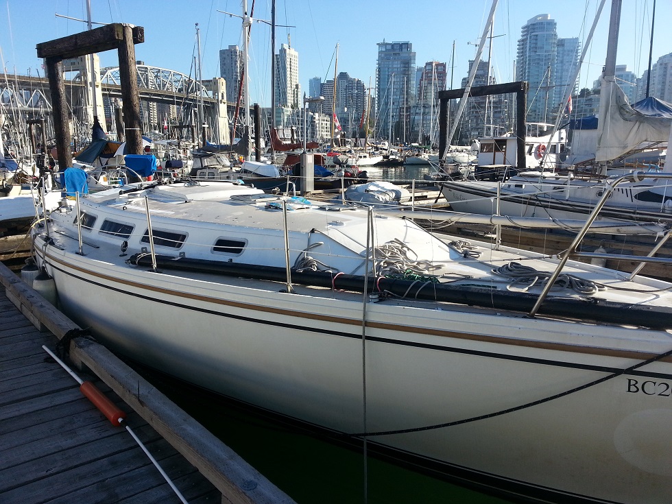
My 1983 boat has had a problem with mast step compressing since I bought it in 2009. Basically I was down to the last 5 threads or so on the upper shroud turnbuckles right from day 1.
This summer, we had 5 days in a row of heavy wind (25ish knots) upwind sailing in steep waves to get home. Foolishly I carried my 135% genoa for much of this, and a single reef. The boat took a beating.
By the time we finished, the top edge of the main bulkhead had sheared off it fasteners - admittedly these appeared to be #10 self tapping screws - shifted a good 3/8" or more to the right, and I had taken up the last few turns on the turnbuckles to keep the rig tight. Additionally, stress cracks opened in the floor all around the mast step. All this movement allowed the boat to flex rather a lot, and we found that by the third day most of the handrail attachment points were leaking in the cabintop, as well as a few other fittings including EVERY chainplate. Time to do something about it.
I started by pulling the rig, which in the PNW is harder to arrange than you might think. But we got it out with the help of the Granville Island Boat Yard which I highly recommend if you are in Vancouver.
Jason V
Vancouver, BC, Canada
Then I cut out the floor pan around the mast step. This was easy with an oscillating multi tool like a knockoff Fein Multimaster. Great tool by the way.
I was expecting to find a stack of rotten plywood, based on a C30 I looked at a while ago. Instead, I found a block of totally rotten and wet red cedar. It mostly came out like that mulch stuff that people put in their gardens. I filled two ice cream buckets with mulch and splinters, then was able to just grab the block and pull it out. No glue, no fuss. All soaking wet.
What I believe precipitated this is that the drain paths out the bottom of the mast are TINY and were totally plugged with dirt, lint, dust, etc. Water would stand inside the step, and the step was held in place with four 5/16" lag screws through the floor and into the cedar block, so water would wick down these screws and enter the wood easily that way. Of course, the cedar block was not treated or sealed in any way so it was only a matter of time.
Anyhow, the cedar block was sitting on top of what looked like a fiberglass-covered chunk of wood spanning the keel sump, and that looked OK so I was hopeful the demolition stage was over already.
Jason V
Vancouver, BC, Canada
Then I made the mistake of probing a bit at the lower timbers - and the 'fiberglass' layer on top popped right off. It appears to be what my boatbuilder friend calls "bear shit" - leftover polyester resin thickened with leftover sawdust, and often used in boat building to fill gaps. This chipped right off and the timber underneath were exposed.
What I found is three very thick hardwood beams spanning the keel box and bedded in polyester goop. These were wet also, I would assume they wick water up from the bilge if there is more than 1/2" of water in the bilge. However they did not seem rotten except for one soft spot in one corner which I removed. I called a couple guys who would know better and let them talk me out of removing these timbers, so I 'glassed over them after removing any soft spots. The platform formed by these timbers is 12" wide and 11" long.
Jason V
Vancouver, BC, Canada
At this stage I figured out how I was going to build a new step and started laminating pieces of wood together in the garage. Although I was working with a footprint of 12" x 11", some testing showed that the biggest single piece I could fit through the floor cutouts was more like 6" x 11" x 2" so there was going to be some assembly.
I went through options from metal (expensive and my tools were inadequate), hardwood (possible) or really high grade plywood. I leaned toward hardwood but received a lot of advice to go plywood, and that is easier to work with so I did that. I the end I planned out to assemble a block matching the the 11 x 12 footprint and 3" thick (assembled in 4 pieces) and and then top it with a block matching the shape of the floor cutout I made, and about 2.5" thick.
I cut these out and took 3 days to epoxy saturate them as much as possible.
In the meantime I went to work on the loose bulkhead.
Jason V
Vancouver, BC, Canada
The bulkhead is formed in two major pieces - the bulkhead itself, and the cornerpost which goes around the mast and forms the corner of the head enclosure. The cornerpost is made from two solid wood planks glued together.
The bulkhead is held in place by the chainplate bolts on the side, six 3/8 bolts (really machine screws) along the bottom into the liner, and 4 #10 self tapping screws along the top. It fits into a dado'd groove in the cornerpost at the right hand side.
The cornerpost is just held in place with 6 self tapping screws, 3 top and 3 bottom. In my boat this was all rubbing and flexing everywhere, making horrible groaning noises, and not doing any structural work.
Once the corner post was out, the bulkhead slid to the right and popped right out of its groove. No evidence of any adhesives was found anywhere.
Jason V
Vancouver, BC, Canada
I reinstalled the bulkhead in two steps.
After all the mating suraces were cleaned and sanded, I slid the bulkhead back into place. I used a hydraulic jack to push the bulkhead up and to the left, mating the outer and upper edges as tightly as possible, and drilled 3/8" holes to through bolt this connection. Then I pulled it back out and applied West epoxy to all the mating surfaces. I think if I was doing it again I would use 3M 5200 as it fills gaps better, but I already had the epoxy.
One thing to keep in mind is that the front face of the bulkhead is covered in arborite, which doesn't stick well to anything. I couldn't remove it without damaging the plywood, so I scored the surface with X's using my cutting tool.
I jacked the bulkhead back into place with the glue in place and bolted the top in. I had to cut some 'flats' into the front flange face for the nuts to push on. I used the same multitool with a plunge cutting blade for this.
When the top was bolted in, I looked at the bottom holes and they were misaligned by about a half inch! I used the deck stay turnbuckle from the cabintop, tied a low stretch line through the mast-wire hole in the settee, and pulled the turnbuckle tight to bring the cabintop and floor closer together. A lot of turns, but I got the holes to line up.
I replaced the six 3/8" bolts in the lower edge of the bulkhead, and added an aluminum flatbar backing plate to spread the pressure out. In all cases, I used bolts with long un-threaded shanks so that they wouldn't saw on the wood bulkhead, and I used hex-head bolts so that I could actually torque them up a bit. The factory used flat-head machine screws, fully threaded, and acorn nuts which could not be tightened enough.
Once the chainplate was reinstalled, all the mating surfaces were basically 'clamped' by the through bolts so I think I will get some decent bonding. The top three holes in the port upper chainplate had become quite ovalized as the bulkhead moved around, but I over drilled the holes and filled them with thickened epoxy, then re-drilled when everything was lined up right. Hopefully that will be good enough.
End result: main bulkhead is epoxied in place everywhere possible. It has:
- Three 3/8" through bolts along the deck
- Six 3/8" through bolts along the bottom plus improved backing plate arrangement
- No threads meeting wood along the chainplate bolting interface (reduced 'sawing' if it does move
The cornerpost got roughly the same treatment. I was only able to add one through bolt at the top for geometric reasons, and the lower bolts had to be carriage bolts to clear the mast. However, I epoxied the top and bottom faces, and epoxied the whole groove that mates to the bulkhead. I think this will make it much stronger. The one self-tapping screw that I couldn't replace with a through bolt got instead a 1/4" square-drive self tapper so it is much stronger than before.
If you go back up to the picture I attached earlier in the first post of this thread, you can see the gap at the bottom of the cornerpost. This gap is GONE - the whole assembly fits tight in place now.
Jason V
Vancouver, BC, Canada
By now I was done woodworking in the garage too. The new platform is pictured in the back of my truck. I was not able to make any very complicated joins in these pieces again due to the problem of fitting them into the bilge. For the side-side alignment I pegged the pieces together with dowels, and the for the stacking arrangment I countersunk some screws into the pieces as I was stacking them. All this had to be done in the bilge.
The whole mess was put together by sliding each layer into the bilge, coating the mating surfaces in epoxy, and sliding them together, then doing the same with the next layer and then screwing them down onto each other. The screws were buried in epoxy and always placed so that the piece going on top would hide the heads anyways. I don't expect to get any water into the wood.
The whole stack went in on top of a bed of short strand polyester filler. Have to be careful as many polyester products will not cure in the presence of curing epoxy, but I have tested this particular combo before and it does work.
The top of the stack comes right through the floor and I will not be attaching them together, I don't believe the floor adds much strength to the system and I do believe the floor/hull clearances are prone to moving, this way I don't anticipate any new cracks being formed.
The final step of the day was bore four 5/8" holes down into the stack, fill them with epoxy, and stick 5/16 bolts into them upside down. These will form the studs to mount the mast step itself, and doing it this way I hope to prevent water travelling down the studs and into the wood, which as mentioned I think caused a lot of my problem to begin with.
Jason V
Vancouver, BC, Canada
Nice work, been there done that. Mine had one solid chunk of hardwood under the mast step. I dug it all out and made a platform with a 6" diameter piece of schedule 80 aluminum pipe capped on both ends with 1/2" aluminum plate. Then filled the void with epoxy mixed with sand. Still have the problem of the deck pulling up. Next project is like yours, I need to tab in the bulkheads so the hull and deck wont flex.
Carl Wehe
1985 C36TM #443
Hillsboro Inlet,FL
I had the same problem. I replaced mine with a pure fiberglass box, built up slowly. Cost about $2k for the fiberglass repairman to do the whole job but he did a good job. I really didn't want any more wood below the waterline, after that little fix-it adventure.
The only thing is that the mast still sinks down about 3/4 inch when placed on the box...wasn't expecting that...but the good news is that it isn't sinking any lower each month, so I think (hope) I'm ok, especially since Larry et al said that those wood cross beams aren't structural - only used by Catalina to help fit the keel correctly during the initial build.
...so I'm thinking all I have to do next time I pull the mast out is to wedge/hammer another 3/4 inch piece of fiberglass (starboard?) between the floor and the fiberglass box, and the mast will then be in the right spot vertically. Till then I can live with it.
I've attached a pic of it.
Ben Ethridge
Miami, FL
1984 MK1 Hull# 263
I want to thank Jason for taking the time to add all that info to the forum here where it will be much better referenced than the email list.
Duane Ising - Past Commodore (2011-2012)
s/v Diva Di
1999 Catalina 36 Hull #1777
Std rig; wing keel, M35B, Delta (45#)
Punta Gorda, FL
http://www.sailblogs.com/member/diva-di/
Possibly even a better spot for it would be in the Upgrades or Maintnenace Section of the website? All photos could be included in one larger article. Just a thought.
Tom Sokoloski
C36/375IA Past Commodore
Noank, CT
Tom, I PM'd Jason about getting this into 1 document for the website.
Thanks, Tom, for the prompt, and Bud for the offer to get it into a real Tech Article. I didn't want to make the suggestion since I was not able to offer to do it.
Duane Ising - Past Commodore (2011-2012)
s/v Diva Di
1999 Catalina 36 Hull #1777
Std rig; wing keel, M35B, Delta (45#)
Punta Gorda, FL
http://www.sailblogs.com/member/diva-di/
Great article Jason. I may be dense but how does the water that comes down inside the mast drain from the step into the bilge ?
Tom Irwin
North Saanich, BC, Canada
1983 Catalina 30 - #3134
Until June 10, 2013
Future Catalina 36 MK II owner
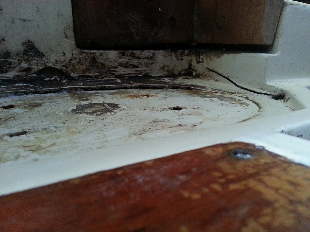
Originally, the drain path is out the hole in the center of the mast base fitting, and through a channel out the left side of that fitting. Then the water would theoretically collect in the pan on the floor, and run out the 4 corner holes into the bilge.
My mast step fitting was full of dust and crud about 1/2" deep, so no chance of proper drainage, and hence my theory that the water was weeping down the lag screws holding the step in place.
This pic shows the step. You can see the large hole in the center, and looking closely you can see a notch in the bottom of the step coming off the left (top in the photo) side of the hole. This notch is the drain path - not very adequate.[IMG]http://www.c36ia.com/forums/attachment.php?attachmentid=1458&d=137961146...
I plan to drill a couple holes right through the mast and step fitting to increase drainage before re installing.
Jason V
Vancouver, BC, Canada
A few more pics.
These show:
- The forward (head) side of the through bolts holding the top of the bulkhead in place. I need to paint these and clean them up a bit but I thought I should show how I created flats
- The lower bolts holding the bulkhead to the front of the dinette. This also shows the lower two through bolts on the corner post
- the new backing plates for the top 3 chainplate bolts, port side, inside the head cupboard. This is 1/4" aluminum angle stock slid into the cupboard and butted up against the cupboard front - just fits. When I tried to tighten these up with just washers the white laminate and the plywood began to crush immediately.
Jason V
Vancouver, BC, Canada
[QUOTE=Nimue;19663]Originally, the drain path is out the hole in the center of the mast base fitting, and through a channel out the left side of that fitting. Then the water would theoretically collect in the pan on the floor, and run out the 4 corner holes into the bilge.[/QUOTE]
In another post, I talk about another way to do this, draining into the shower pan, so as to keep the bilge completely dry:
[url]http://www.c36ia.com/forums/showthread.php?t=2033&highlight=shower[/url]
After about 6 months, this is working out just fine.
Ben Ethridge
Miami, FL
1984 MK1 Hull# 263
Ben, your setup is pretty slick and makes sense if you are 90% of the way to a dry bilge. I don't have dripless packing, but more importantly I run a dehumidifier in my boat 24/7 at the dock and the outlet runs in to the bilge, to be removed by the bilge pump. No dry bilge for us.
While the rig was down I took the spreaders home and painted them. Around the flag halyard (SS eye strap screwed in to the aluminum) there was a lot of pitting and the paint was all gone. To prevent recurrence, I drilled just one of the mounting holes a bit bigger and pulled a loop of dyneema through. the other end of the loop is just tied with a diamond knot, like you'd use on a soft shackle. Aside form hopefully reduced corrosion here, I should also eliminate the rattle of the halyard block against the metal eye strap.
Rig should stand up today!
Jason V
Vancouver, BC, Canada
Mast went back up this morning. Not pulling anything to full tension for a few more days as I want to give the epoxy 10 days to set up fully, but I wound up the upper shrouds a little bit and they started to look tight-ish with the turnbuckles half way on, so that is good news. I added a 2" toggle to the forestay to make up for the added height of the mast step, and hopefully get me a little more mast rake which I wanted anyways.
Still have to replace the port aft chainplate, re and re both forward lower chainplates (leaking) and spend an afternoon up the mast putting on spreader boots, windex, vhf whip, trimming marks on the spreaders, probably something else I've forgotten, but I had a 2 week 'favour' called in to store the mast and I made it with a day to spare. Now the rest can proceed at a more leisurely rate - winter racing starts in 4 weeks.
Jason V
Vancouver, BC, Canada
To follow up, finishing touches went on last night; spreader boots, windex, VHF antenna, flag halyards, that sort of thing. The I finally pulled the rig tight and tuned it up.
End result, instead of just endlessly winding the turnbuckles to slowly tighten things, the rig went from floppy loose to sail-able tight in 3 turns on the uppers. That is a significant change. And not a creak from any floorboards inside the boat. I think we are better than new - for now.
Next up, new instrument though hulls, remove the vestigial thru-hull from the direct-overboard head discharge (seacock is shot anyways) and then, with luck, STOP SPENDING MONEY!
Jason V
Vancouver, BC, Canada
[QUOTE=Nimue;19871]... and then, with luck, STOP SPENDING MONEY![/QUOTE]
Sorry to hear you are getting out of boating, Jason. ;) I mean, that's the only way I know how to stop spending money on a boat.
Seriously, it must feel good to know all that hard work paid off. Good job!
Duane Ising - Past Commodore (2011-2012)
s/v Diva Di
1999 Catalina 36 Hull #1777
Std rig; wing keel, M35B, Delta (45#)
Punta Gorda, FL
http://www.sailblogs.com/member/diva-di/
[QUOTE=deising;19872]Sorry to hear you are getting out of boating, Jason. ;) I mean, that's the only way I know how to stop spending money on a boat.
Seriously, it must feel good to know all that hard work paid off. Good job![/QUOTE]
You're right of course, I have a plan to add dual backstay chainplates so that I can build a backday from Dynex Dux this year. $7.50 per foot. Better make us go upwind in waves a fraction of a fraction faster!
Then the Kiwigrip...
Jason V
Vancouver, BC, Canada