
So far I have not found this question answered here, but I am working my way through every forum post that mentions batteries and wiring still. There are a lot, so bear with me on that (and if already answered reply with a link to it!).
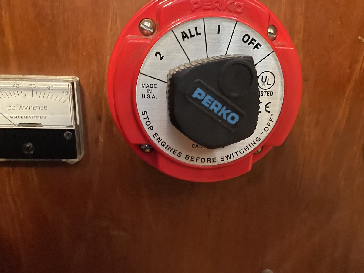
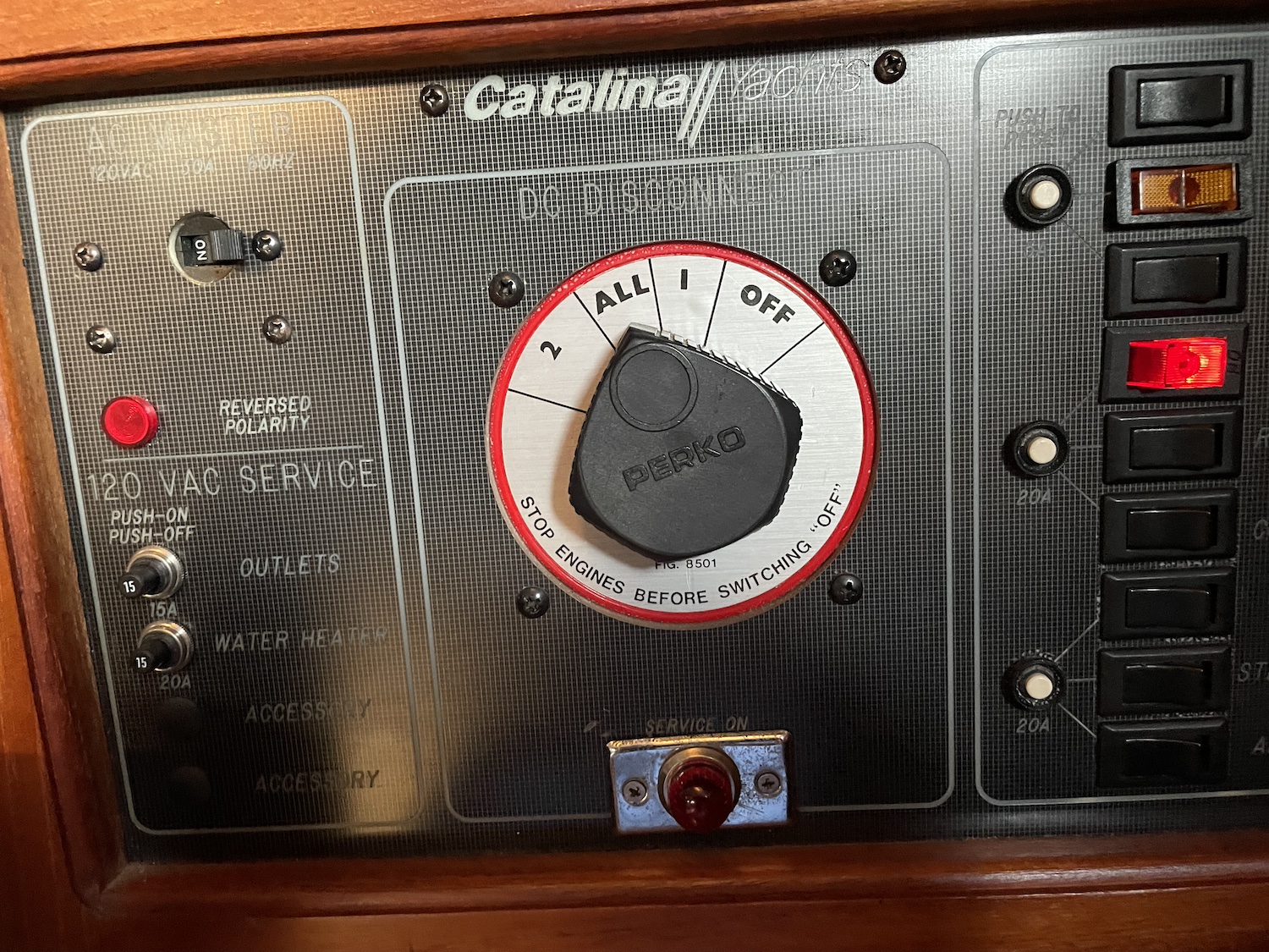
Per my sig line (if it shows up?), I bought a 1988 C36 late last year that I am addressing a few issues on. It came with golf cart batteries under the starboard seating just forward of the nav desk and a separate starter battery under the aft bed. I am replacing the starter battery because it was cracked and not functional. But, my question is based on the fact that there are two 1,2,All switches, one at the main panel above the nav desk and the other just "port" of the stairs (attached below hopefully)
I realize that this is just like guitar and amp wiring (another of my hobbies) with tons of possible customizations and that there really is no real way to know what these do without actual testing / looking at wiring. That said, my question here is whether there is a default wiring (and did the boat come from the factory this way? No idea.) scheme that this mixture of switches is known to be (or often) used for? I've read articles that explain how the 1, 2, ALL switches work, but I've yet to find anything written about how two of them would be combined and how they would interact given all of the possible settings between the two.
I'm imaging a 4x4 table with the 4 settings across the top (columns) and the 4 settings again for each row meaning that there are 16 possible different settings to ponder here. Geez, is it this complicated? Or, do the two switches not even interact and that imagined table is completely not applicable? Even if that were true, I have no idea what 1, 2, All would mean for just a single starter battery unless someone just used the 1, 2, All switch for an On/Off switch because they already had it vs buying the simpler on/off switch?
Perhaps someone can jumpstart me on the path to righteousness here? That would be appreciated. I will do the testing to see what/how things are wired, but if there is a default (like there is with amps and guitars) that would be a good education for me given how new I am to all things sailboat ownership. Loving it though!
Gerald Hinson
Seattle / Shilshole Marina
1988 Catalina 36 MK1 (#832)
I think the only way you will find the answer is through testing. It doesn't seem like the boat would originate from the factory this way and that the previous owner likely added the second switch. Maybe they were creating a means of isolating each of the three batteries and have the ability to add one at a time? Only a guess.
Paul & Wendy Keyser
"First Light"
Rye NH
2005 C36 MKII #2257
Wing, M35B
Hi Gerald,
I have 1985 C-36. I added a separate starting battery and a second battery switch. I works like this.
Switch #1:
Pos 1. Main House battery bank
Pos. 2 Auxillary battery bank
All connect Pos. 1 & Pos. 2 together
In all cases the output goes to the DC circuits and to Battery Switch # 2
Switch #2:
Pos. #1 Starting battery
Pos. #2 Output from Switch #1
All connects Starting battery and whatever output Switch #1 is set for.
That system assures the engine will have enough juice to start the engine. Normal setting is both switches are set to Pos. 1.
Hope this helps
Lou Bruska
Sojourn
1985 C-36 Mk-I TR #495
Eldean Shipyard
Lake Macatawa (Holland, MI) Lake Michigan
Rallyback@comcast.net
I have seen this done many times before. Including by the po on my current boat (2000 36 mk2). If I had to guess let's call the switch on the main breaker panel switch one and the other switch 2.
switch one in position one will "turn on switch 2"
switch one is position 2 is probably the battery under the birth that is cracked
switch 2 will split up the 2 golf batteries
if that's not right try the opposite.
example: swich one on all, swich 2 on 1
would be the cracked battery and one of the golf batteries
if all else fails get a multi meter and switch it to continuity clamp to a post on the back of the switch and touch the other to the hot on each battery to identify which wire goes where. If I get a chance I can draw a diagram for you detailing the tongue twister above
I did a bit of testing after I wrote the original post above.
With Switch 1 defined as "Main panel switch" and Switch 2 being "standalone switch between stairs and frig" this is what I found:
Switch 1 in any position will turn on the lights, etc. in the cabin. It will not start the engine in any position.
Switch 2 is the opposite. Any position will start the engine. None of them will power the lights, etc. in the cabin.
From what I can tell they aren't wired together in any fashion.
I replaced the cracked battery. Next projects are to fix the rub rail where it has some damage and figure out if the ringing sound I hear at some RPMs but not others is the infamous "prop singing" or something else. Runs great and if I rev it higher the noise mostly goes away.
Gerald Hinson
Seattle / Shilshole Marina
1988 Catalina 36 MK1 (#832)
Gerald,
I would recommend taking the output of Switch 1, battery 2 and connecting it to the input of Switch 2. That way in an emergency you'll be able to use the "House" bank to start the engine.
Lou Bruska
Sojourn
1985 C-36 Mk-I TR #495
Eldean Shipyard
Lake Macatawa (Holland, MI) Lake Michigan
Rallyback@comcast.net