

This afternoon I went up the mast to replace my Raymarine radar scanner and I took the opportunity to take a few photos showing my radar mount base, and to capture a view into the conduit. The photos attached show some interesting things:
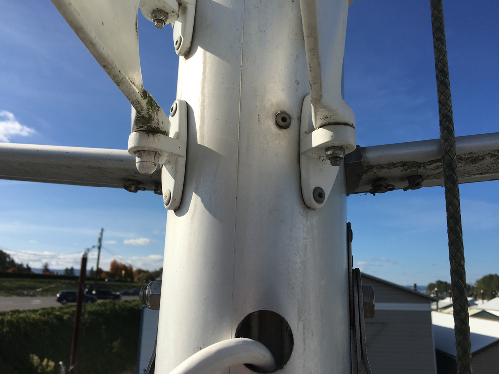
* I chose to mount my radar so that the beam was slightly above the spreaders. I did not want the metal spreaders to interfere with the beam - metal is very reflective to X-band radiation - so I made sure at the original installation back in 2002 to mount high enough so that the radar beam could pass undistorted above the spreaders. I also made sure that my radar reflector was NOT located at the height of the scanner. Note that for this upgrade to a new Raymarine HD radar I was able to re-use my original Raymarine scanner mount, even though the new radar scanner is about 2" larger outside diameter.
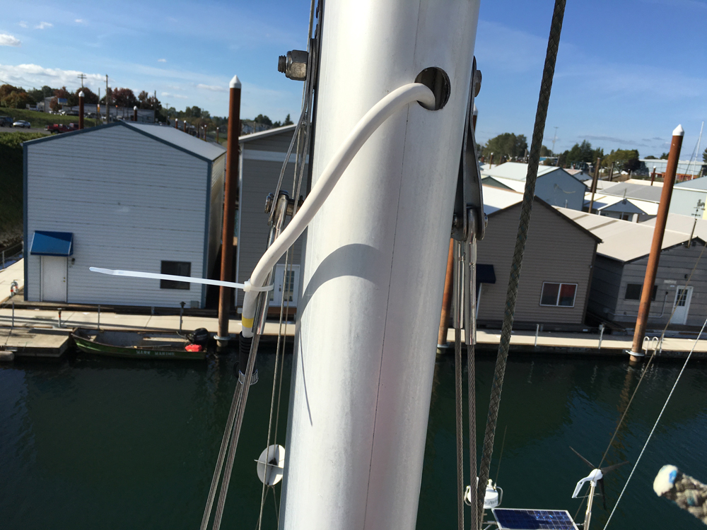
* You can note the location of my scanner mount base and the location of an approximately 2-inch dia hole cut into the mast and mast conduit. You can judge the location of this hole by noting the lower shroud tangs nearby.
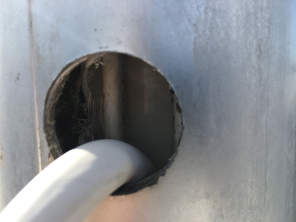
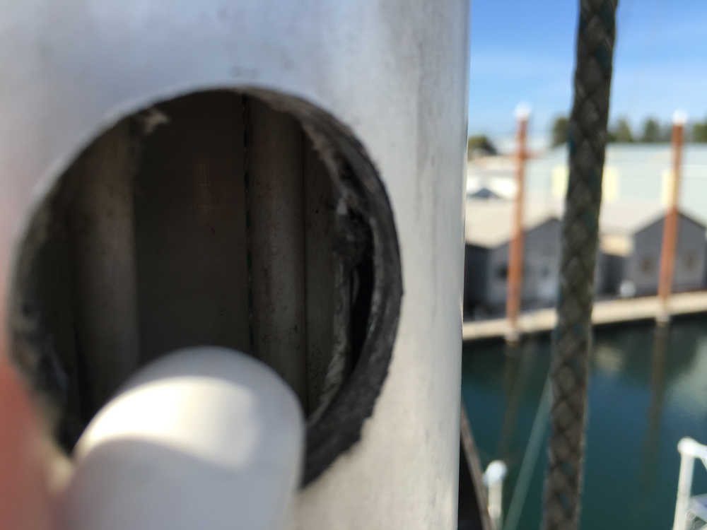
* I took a couple shots into the conduit with my iPhone. It seems like the conduit is most likely ~ 2-inch PVC pipe. - AS I look more carefully at my photos I believe now that the conduit is aluminum, not PVC.
* After cutting it at the base of the mast, I pulled the old cable out through that hole at the spreaders, and as the old cable came out it brought one end of my new 50 ft plastic 'fish' that I got at Home Depot. I then used that fish to lead the new radar cable down the mast. The new cable has a connector on the bottom (non-scanner) end of slightly more than 1/2 inch diameter. All went well leading the new cable down inside the conduit until about 12 inches above the mast step where SOMETHING caused the connector/fish bundle (which I hadn't faired properly) to hang up. An application of s-i-g-n-i-f-i-c-a-n-t (read 'reluctantly high') pulling force finally forced the fish and connector through. I was pushing and manipulating the cable like crazy at the spreaders, while my buddy pulled strongly at the mast step. (The small 10-pin data connector may have been damaged by this reluctant force, but if so I will bring the individual wires to a terminal block near the mast step. I may do that anyway.)
* NOTE TO SELF: Take extra care to properly FAIR any small bundle going through the mast conduit.
* In one of the photos you see the new radar cable tie-wrapped to a shroud. After all that work I didn't want to lose my end of it while I installed the new scanner.
* Looking into the conduit you'll see a surprising amount of room. In my photos you'll see in addition to (1) my new radar cable, (2) a coax for the masthead VHF antenna, (3) a two conductor cable for the anchor light, and there is (4) a messenger line to the masthead that was left in place back in 2002, and which I will use in a few days to lead my new Raymarine wind sensor cable down from the masthead. I am confident that there is entirely adequate room remaining for the wind sensor cable, and possibly even for another small cable should anyone ever decide to, say, put a tri-light (or in another part of the world, a lightning dissipator?) up there.
I hope this helps to visualize what's available to you folks inside your mast.
Larry Brandt
S/V High Flight #2109
Pacific Northwest, PDX-based
2002 C-36 mkII SR/FK M35B
Thanks, Larry. I didn't know the conduit was even there. What is it for? Electrical wires or halyards? Both?
Ben Ethridge
Miami, FL
1984 MK1 Hull# 263
Electrical only. Halyards run outside the conduit.
Larry Brandt
S/V High Flight #2109
Pacific Northwest, PDX-based
2002 C-36 mkII SR/FK M35B
Larry,
As always, great stuff. I have not figured out where the words come out at the mast step. Would you have a picture of guidance on that? It looks like it comes out forward of the bilge.
2000 C36 MKII 1825
OK, you asked for it. These photos are going to gross you out: an accumulation of grime, dirt and cat hair...
Note that the storage compartment in the photo is under the seat you get with the U-shaped dinette arrangement.
Larry Brandt
S/V High Flight #2109
Pacific Northwest, PDX-based
2002 C-36 mkII SR/FK M35B
Thanks. Looks like you have the pedestal table. We have the wires with the black sheath in common. I think the rest of mine come out down in the bilge. I'm going to get in there this weekend.
2000 C36 MKII 1825
Larry,
Great photos/documentation.
Steven Jones
C36/375IA FaceBook group administrator
C36/375IA Jib Sheet Editor 2012
Seal Beach, CA, USA
C36 #2164 Maléna 2003 Mk-II SRig/FullK, Long Beach, CA
stevenjones21@gmail.com