

Not sure how previous owners have managed without a windlass but after 26 years I think that it's time. I purchased a Maxwell RC88 vertical windlass for chain/rode. (Low profile) I've looked through the information that I could find on installations, but mine seems to be a little different.
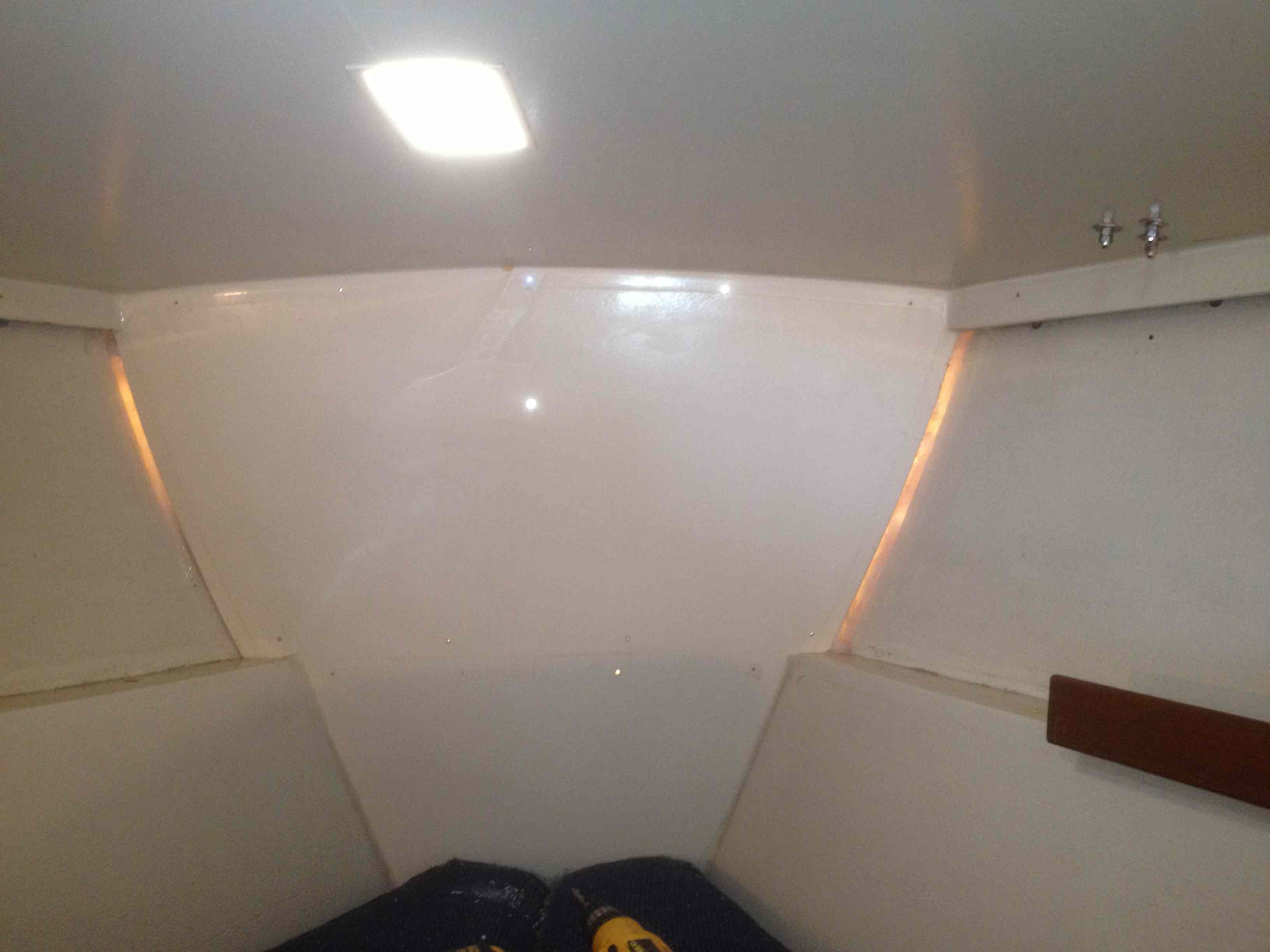
I removed the wooden paneling on the inside of the V-birth and was surprised to see that there was no plywood panel as has been described. There is only a fiberglass bulkhead that is the separation with the anchor locker. The bulkhead looks the same on the inside of the locker- just a flat panel with no molded protrusions as I see on other's installations. This is clearly not structurally strong enough to provide any support for the forces of a windlass.
Further forward (about 12") there are angular protrusions on either side of the anchor locker that appear to be intended to to support a Danforth anchor. They are quite robust and would seem to be a good place to add support back to the bulkhead. The problem is that they are completely enclosed so it is not possible to bolt through them.
My plan is to attach a 30" x 19" 3/8" aluminum plate to the the bulkhead on the anchor locker side bolted to ample backing plates inside the vbirth. This will add the necessary rigidity and strength to the bulkhead. Then I plan to add extensions from this plate to the protrusions in the anchor locker to provide support to the bulkhead against the forward force/pull of the windlass. On top of this structure I will add a plate for mounting the windlass.
I plan to use aluminum since this aligns with my skills; surfaces will be either epoxied or powder coated.
I am curious if anyone has a similar configuration and how they may have solved the installation? I am also interested to know if there are any reasons why I should not make openings in the angular protrusions to enable me to bolt in supports? I need to make openings large enough to add nuts and back plates. I can glass over the openings if necessary.
Paul Meyers
1986 Catalina 36
Hull #615
Ventura, California
Paul, don't know if any ideas in this might help. Good luck. [url]http://www.c34.org/projects/projects-anchor-windlass-apache.html[/url]
Stu Jackson, C34IA Secretary, C34 #224, 1986, SR/FK, M25 engine, Rocna 10 (22#)
Thanks Stu,
I spent some time with that installation and it does help in some areas. The anchor locker in this article is different and seems to be stronger with the protrusion for the anchor located on the bulkhead. My installation looks hinky, in that something was done post production. The corners in the rear of the anchor locker have been reglassed in a way that appears to try to correct a mistake in construction. The surveyor looked at it when I got the boat but just indicated that he was satisfied with whatever had been done.
Do you think that there is any concern in opening the protrusions minimally as I described?
Paul Meyers
1986 Catalina 36
Hull #615
Ventura, California
Paul, a minimal opening can simply be a thin drill to see what's there. One of the access "tricks" for those of us who needed to add cleats at the bow was to install a 4 inch round Beckson opening plate. If you have the room, that could give you enough access to install bolts and backing plates.
Stu Jackson, C34IA Secretary, C34 #224, 1986, SR/FK, M25 engine, Rocna 10 (22#)
The Beckson plate is a good idea as long as I have the area to attach it and still mount a support. A 4" plate requires 6 sq. inches. Not at the boat so not sure. I am assuming that the inside of the anchor locker is only a liner and not for structural support; I'll verify that with a call to Catalina tomorrow. If so there should be no problems with opening the protrusions enough to attach some backing plates and nuts.
Paul Meyers
1986 Catalina 36
Hull #615
Ventura, California
Paul,
I am in the process of planning an install of a windlass and would like to install it in the locker as well. I think i can offer a bit of insight at to what you are seeing in the forward section of the vberth and what the PO did. the way the bulkhead was attached was not the best in the world on the older model of the Mark I (can't speak to any other model) (hull # 226). But i had a continuing battle to prevent water from running down the back of the bulkhead, the front of the v-berth, until I glassed in everyplace i could find that had any type of exposure. I believe the original idea was to tab the very thin piece into place and leave space to run wiring etc through the section of between the bulkhead and the sides and deck. I had read and tried a number of methods to prevent water from getting into the v-berth area without any success. thus my attempt to glass that section of the anchor lock. I haven't had any leaks since. In my effort to prevent the leaks I also added some stringers to the bulkhead with the idea that they would provide additional support when and if i did add a windlass. My thought was that i would be able to use the back of the fiberglassed section that holds the danforth anchor and the front of the bulkhead in addition to fiberglassing the platform to the side and provide adequate support for a windlass. good luck on you project. I believe that you will find that the right angle sections of the anchor lock will work well and support the windlass.
Mike Hogan
s/v Ciscocat #226
Mark I XP25, std rig
Mike,
Thanks for your post, it really explains a lot; nice to be able to resurrect some history on my boat for your experience. If you look at my picture, each side of the fiberglass bulkhead is translucent. The reason is that someone put a massive silicon bead on each side probably to cure the problem that you had with leaking and that you solved by glassing. The corners of the bulkhead inside of the locker were roughly glassed. Apparently the silicon and glass repair worked since I have not had any water in the time I have had the boat.
I will post some pics when I install the structure that I have in mind; I think that it is similar to what you have in mind.
Paul Meyers
1986 Catalina 36
Hull #615
Ventura, California
Paul:
I am very interested in what you decide to do, and hope you can favor us all with some good photos. I have this project in mind, as well.
It sounds like you have seen some of the write-ups on the C36 and C34 sites. Within the last year or two, I know I've seen a write-up for a similar windlass install in Mainsheet, but for a smaller boat (C30?). If you have those magazines sitting on the shelf, you might leaf through and find it.
I'd also be interested in knowing what you intend to do about wiring, and your battery source.
--Nelson Lee
Nelson Lee, "Stella," 2002 C36, hull 2069, Universal M35BC, berthed Sausalito, CA
Nelson,
I'll take pictures of everything and post them. Since my anchor locker is configured a little differently than the pictures that I have seen in the various articles, what I do is going to be a little different.
As part of the installation i am going to cut away the anemic anchor rollers that came on the boat and replace it with a decent anchor roller. There is a good article on this on the C34 site.
[url]http://c34.org/wiki/index.php?title=Windlass_installation_w/_bow_roller_...
Also shows a really nicely crafted windlass installation,
My plan is to bring the wiring back to the two house batteries. I haven't given it any more thought than that; if you have ideas would appreciate it. The windlass came with an up/down solenoid, and a 135 amp isolator breaker. The wiring diagram in the manual looks pretty straight forward. Will use the recommended 4 awg for the power runs. [COLOR="Red"]Wrong[/COLOR] (When I posted this, I was not considering the run in both directions: I ended up using 2 awg)
Paul Meyers
1986 Catalina 36
Hull #615
Ventura, California
i never considered using SS for the fabrication but what a great idea, just need to be careful in making the template and insure adequate support. alot easier that making up a fiberglass and marine plywood platform. 1/8" inch provides enough support? the stuff I've seen from folks like garhauer seems to always be at least 3/16". ????
Mike Hogan
s/v Ciscocat #226
Mark I XP25, std rig
Sorry for the delay in following up on this installation. It has taken longer than expected; part of the problem is that my boat is 3 1/2 hours away. Throw in the holidays and things slow down. I have finished installing everything with the exception of putting things back where they were. I have included some pictures and some explanations of what was done and why.
To review I wanted to do a new install of a windlass, and chose a Maxwell RC8, which is a vertical windlass sized correctly for the C36. My boat had not had a windlass previously. The windlass was to be installed in the anchor locker and completely covered when the doors were closed. I examined accounts of many installations on both the C34 and C36 sites.
Most of the accounts described removing the paneling on the inside of the V-birth to reveal a stout plywood sheet attached to the anchor locker fiberglass bulkhead. When I removed my paneling, there was nothing other than the fiberglass bulkhead, it was not very thick and was definitely not adequate to provide any support. (Picture below) I considered adding ¾” plywood to the interior, but this would have required that I refit the woodwork in the v-birth. Also, given that the bulkhead was not molded to the anchor locker, it would not have given me the needed strength. It made more sense to add a support to the inside of the locker which could also be the foundation for the support of the windlass. This was especially important on my installation since the anchor locker is pretty sparse structurally compared to other installations that I viewed.
I decided to use 3/8” aluminum since I had almost a half of sheet on hand and it could be easily cut for the most of parts that I would need. (All cutting was done with the skill saw and a metal cutting blade.) I have included a rough sketch below that I did early in the process. I would mount a substantial plate to the fiberglass bulkhead inside of the anchor which would be backed by two aluminum bars on the inside of the vbirth. (Pictures below) This would strengthen the fiberglass bulkhead considerably. From this plate I would extend two perpendicular arms to the triangular shaped inside the anchor locker, attached with aluminum angle. These arms would provide horizontal support to the bulkhead and counter the forces of the windlass. Additionally, the arms would provide a platform for a plate on which the windlass would mount. It became apparent that measurements were pretty irregular from one side of the anchor locker to the other and everything would have to be carefully fit. For this reason I decided not to try and fabricate a single piece and weld it, but to put the structure together in parts that would be bolted together. In this way I could fit all of the parts into the anchor locker and make adjustments at the boat so they fit perfectly. This fitting was done over the course of a few trips. (I'll add some more info and and pictures in a followup post)
Paul Meyers
1986 Catalina 36
Hull #615
Ventura, California
Paul,
Are you sure that 4AWG is recommended? That sounds awfully small to me. The round-trip length of the wiring has to be at least 35-40 feet, and if you are using a 135A breaker.....
[URL]http://www.westmarine.com/webapp/wcs/stores/servlet/WestAdvisorView?lang...
If you haven't bought the wire yet, you might want to consider going up a size or three. Just a thought.
Tom Sokoloski
C36/375IA Past Commodore
Noank, CT
In the picture below, the arms are attached to the aluminum plate on the bulkhead and extend out to the triangular protrusions. Each attachment is a piece of angle attached to the arm, providing both forward and lateral stability. I cut an opening in each protrusion in order to attach deck plates allowing me to put in backing plates and to attach nuts. (Stu’s suggestion) The two arms provided a platform for the mounting plate on which the windlass attaches.
The next pictures show the whole structure on the workbench inverted. If assembled into a single unit it would not have been possible to install the platform. By being able to break it down, installation was easy and could be fitted to the somewhat irregular shapes. I used stainless bolts, and used lanolin on all of the surfaces where it made contact with aluminum. Most of the holes were drilled and tapped. (A drill press made the job much easier) The following picture is the whole structure assembled in the upright position. The position of the windlass was determined and the openings were drilled with hole saws. The small hole is for a footswitch, but I changed my mind and have installed a pendant instead..
Everything was sanded, acid etched, painted with zinc chromate, primed and finally painted with rustoleum semi gloss. The following two photos show the painted platform installed.
Paul Meyers
1986 Catalina 36
Hull #615
Ventura, California
Tom,
Thank you for the correction. I went back and amended my original post. When I wrote that I was not considering the run in both directions; I ended up using 2 awg.
Paul Meyers
1986 Catalina 36
Hull #615
Ventura, California
I hope it works for you. Electrical drawing in my MKII owner's manual indicates size 0 going to the windlass.
Greg Jackson
SV Jacqui Marie
2004 C36, MKII
tall rig, wing keel,
Sorry for stringing this out, but there is a limit of 5 pictures/post. I installed a piece of tubing through the upper starboard corner of the anchor locker into the vbirth to serve as a chase for wiring. This has to be fairly large to accommodate the large cable.
Pictured below is the windlass installed on the platform.
The electrical installation is complete and almost constitutes a second project; I will followup with another post. I've got to get some other work done today first....
Paul Meyers
1986 Catalina 36
Hull #615
Ventura, California
I went with the manufacturer's specification on the wiring size. This is specific to the load of the windlass and the length of the runs of the cables. I should point out that I am only describing what I did on my boat and not providing advice to others. Since electrical is my weakest area (among others) I was particularly cautious about carefully following manufacturer guidelines in my installation.
Paul Meyers
1986 Catalina 36
Hull #615
Ventura, California
Paul,
Have been able to test your set up with the configuration you have? Does the anchor line feed ok? In reading what I could it sounds like the angle that the line/chain feeds into the windlass is a fairly small angle of attack, if that is the correct way to phrase it. Did you have to make any accommodations to how the anchor rode was feed into the windlass. I have a very selfish motive since I would like to have a similar set up and plan that as one of my projects this winter.
Mike Hogan
s/v Ciscocat #226
Mark I XP25, std rig
Mike,
That's my plan for this weekend, along with flying a spinnaker for the first time.
I installed the windlass as close to the top of the anchor locker as I could and have the doors close, and even added a 1/2" starboard shim to raise it a little more and separate it from the painted aluminum surface. I still have the anemic little rollers that came on the boat, but plan to replace the starboard side of this set up with a much larger/longer bow roller. Larry's survey has been helpful in informing that solution. If there are problems with alignment, or "angle of attack", I can adjust for that when I add the anchor roller.
Paul Meyers
1986 Catalina 36
Hull #615
Ventura, California
did you set the windlass at any type of angle or consider doing so? i have installed a long anchor roller and appears to get the line to feed in the windlass will have to tilted back (the front of the windlass pointing up) by some degree to get the line to feed in properly, this of course is speculation on my part since i don't have a windlass installed yet. just wanted your thought on the matter since you have obviously already install the windlass
Mike Hogan
s/v Ciscocat #226
Mark I XP25, std rig
Mike,
I raised and lowered my anchor in the slip and everything seemed to work fine.
There is a slight downward angle from the anchor roller to the windlass, but it seems to be within working limits. I think that it helps that I installed the windlass as high as possible in the anchor locker The manual indicates that the feed to the windlass from the anchor roller should be on the same plane. This could be easily done by using a 1/2" starboard shim and sanding it at an angle with a belt sander. I am going to install a full sized anchor roller which should be a big improvement over the existing setup. What anchor roller did you install?
Paul Meyers
1986 Catalina 36
Hull #615
Ventura, California
Paul
I installed one from Garhauer I want to say it was one of the longer ones listed on the page below, I wanted to make sure I had plenty of clearance, the one of the biggest hassle was removing one of the old rollers, I used a saws all and several blades and a lot of time. I made sure I went slow as to not over heat the metal. The biggest hassle was setting the bolts there is not a lot of room up forward at the bow. It seems to work well but since my boat lives on a lake there is not a lot of stress on the unit when anchored.
[url]http://garhauermarine.com/catalog_process.cfm?cid=24[/url]
Regards
Mike Hogan
s/v Ciscocat #226
Mark I XP25, std rig
This is what I used:
[URL]http://www.catalinadirect.com/index.cfm?fuseaction=product.display&produ...
Still not long enough for the Manson wiggle it up the last foot sideways issue though. Garhauer's price for the same length/width is better but not sure they give you the backing plate.
Bud,
If you used a 30" roller, what length extends beyond the the bow, not supported?
Mike, thanks for the info on Garhauer, didn't know that they made anchor rollers.
Paul Meyers
1986 Catalina 36
Hull #615
Ventura, California
[QUOTE=pmeyers;16559]Bud,
If you used a 30" roller, what length extends beyond the the bow, not supported?
Mike, thanks for the info on Garhauer, didn't know that they made anchor rollers.[/QUOTE]
6" or so more than stock it fits the existing bolt holes, pretty simple install. I have no concerns about the extra overhang strength wise it is prett stout. Look at the last entry in Larry Brandts anchor survey that is it on stbd side.
I’m going to try and finish up my notes on my windlass installation. The last step was the wiring; while pretty straight forward was time consuming. An excellent source for marine wiring and related products is genuinedealz.com. The prices are good, shipping is included and orders are shipped immediately. (No connection with genuinedealz)
Earlier in this description I indicated that I had used 4-awg cable. When I wrote that I had only considered the run in one direction. When I realized my error and doubled my runs, the table provided by Maxwell indicated that I should increase the cable size to 2 awg. Once my lengths were determined, I cut the wire and compressed lugs in the ends using an impact tool. I then soldered the lugs and covered with adhesive heat shrink tubing.
A big decision was the location of the solenoid. Since the cables are large and hard to maneuver, I wanted some space around it for working and I wanted easy access for the future. I decided to mount it in the open cabinet above the hanging locker in the v birth entry. I epoxied a plywood base and screwed the solenoid to it, and added a terminal block for attaching control wires. The terminal block was attached with a strong velcro to make it easier to pull out for access. Eventually, I will cover the solenoid installation up with a piece of paneling that can be easily removed The loss of storage space is only about 3” deep. (Picture)
In addition to the factory up/down control that I installed in the cockpit, I also added a pendant and wireless control. The pendant was suggested to me in a windlass installation article by Gary Teeter and I really liked the mobility that it provided over a foot switch. I wrote Gary and he was kind enough to send me some additional information. I also purchased a new wireless control on ebay for $60; it came with two fobs with brackets, which I installed in the nav station. (I will add neck lanyards so they don't go overboard.) It was a bit of overkill, but it was very inexpensive to do while I was in the process and provided me with multiple options for operating the windlass.
I installed a waterproof deck fitting in the anchor locker for the pendant. It is a 3-pole plug that is removed when not in use. The receiver for the wireless controller was installed outside of the solenoid location; I was concerned that when it was enclosed it might limit the signal.
Cables were installed in the channel in the upper starboard corner of the v-birth. These will not be visible when the wood trim is replaced. The breaker was installed under the seat in the small settee where the house batteries are located. Everything seems to work great. As I mentioned, previously, the next step is to improve the anchor roller setup.
Paul Meyers
1986 Catalina 36
Hull #615
Ventura, California
paul,
i'll be at my boat this weekend but i pretty sure the roller extends more that 6" beyond the bow of the boat... thanks for all the good info on the installation maybe i'll get off my butt and get mine done
Mike Hogan
s/v Ciscocat #226
Mark I XP25, std rig
I will be adding a windlass to my boat, a 1987 Mark 1 and need to run the electrical wires to the bow. I noticed one area where I would have a problem. My battery is located in the seat back in front of the nav station and when the cable gets to the forward seat there is a problem. The current wiring run is under the front seat and (this is where the 110v wire and vberth lamps go thru a small opening) there is not room for battery cable sized wire there. I drilled an exploratory hole between the seat and the cabinet of drawers and there is a 'stringer' or something for the hull structure. This area is also where the starboard chain plate is attached.
So my question is; how did others run their power cables in this area? did you go under the sole or along the bottom of the forward seat storage area?
Any help on routing would be greatly appreciated.
TIA,
Ralph
Still a Thrill # 765
WK, STD Rig
Lake Texoma, TX